REV : 2
REV DATE : 5/18
DPN004080
Page :1 /1
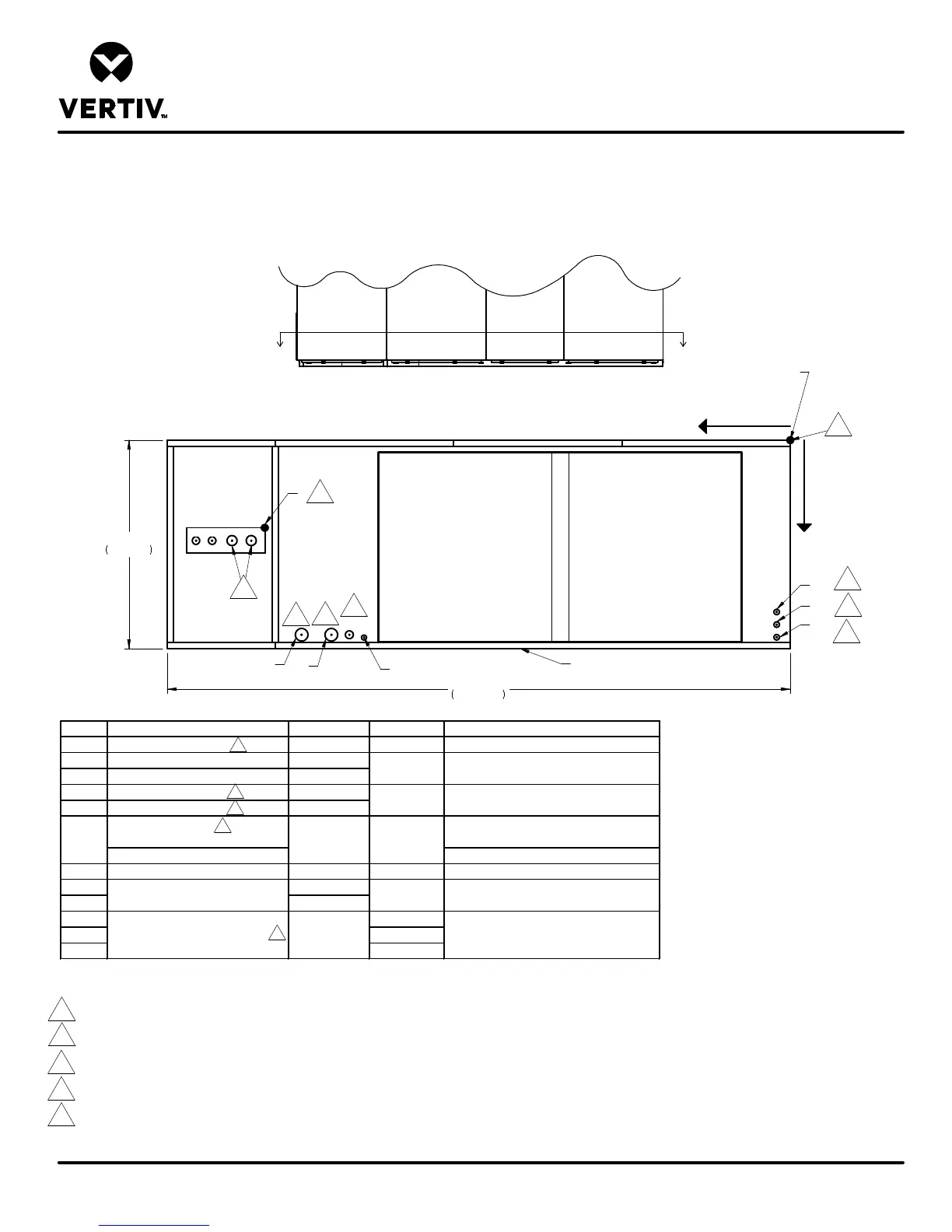
DOWNFLOW DA080-DA085
SCROLL OR DIGITAL SCROLL COMPRESSOR MODELS
Form No.: DPN001040_REV4
PRIMARY CONNECTION LOCATIONS
LIEBERT DSE
L1 L2
G1
G2
O
X
Y
100"
2540mm
CD
POINT DESCRIPTION X in. (mm) Y in. (mm) CONNECTION SIZE / OPENING
R REFRIGERANT ACCESS 82-7/8 (2105) 13-11/16 (348) 15" (379mm) X 5" (127mm)
L1 LIQUID LINE SYSTEM 1 94-11/16 (2405)
L2 LIQUID LINE SYSTEM 2 91-7/8 (2334)
G1 HOT GAS DISCHARGE 1 88-3/4 (2254)
G2 HOT GAS DISCHARGE 2 85-9/16 (2173)
(infrared humidifier or no humidifier)
3/4" NPT FEMALE
W/ OPTIONAL PUMP 1/2" O.D. Cu
HUM HUMIDIFIER SUPPLY LINE 76-1/2 (1943) 29 (737) 1/4" O.D. Cu
E1 78-1/2 (1994)
E2 75-3/8 (1915)
LV1 29 (737)
LV2 30-7/8 (784)
LV3 32 (813)
16-3/4 (425)
16-3/8 (416)
31-3/8 (797)
31-1/8 (791)
5/8" O.D. Cu
1-1/8" O.D. Cu
ELECTRICAL CONN. (HIGH VOLT)
ELECTRICAL CONN. (LOW VOLT)
2-1/2"
7/8"
CD 68-3/8 (1737)
2 (51)
3
2
Front of Unit
Section A-A
Notes:
1. Drawing not to scale. All dimensions from rear corner of unit including panels, and have a tolerance of ± 1/2" (13mm).
2. Field pitch Condensate Drain line a minimum of 1/8" (3.2 mm) per foot (305 mm). All units contain a factory installed condensate trap. Do not trap external to the unit. Drain line may
contain boiling water. Select appropriate drain system materials. The drain line must comply with all local codes.
3. When piping out the top of the unit, install traps in the discharge lines in the bottom of the unit before running lines to the top.
4. Opening for conduit chase, E1 and E2 are openings for conduit for connections to 2-1/2", 1-3/4", and 1-38" knockouts at electric panel.
5. See DPN004083 for alternate piping from the top of the unit. Alternate access is available on all units except 575V.
3
3
2
1
A
A
R
35"
889mm
E1
E2
HUM
LV1
LV2
LV3
EC Fan
Outlet
EC Fan
Outlet
5
5
All dimensions from
rear corner of unit
including panels
4
4
4
4
4
4