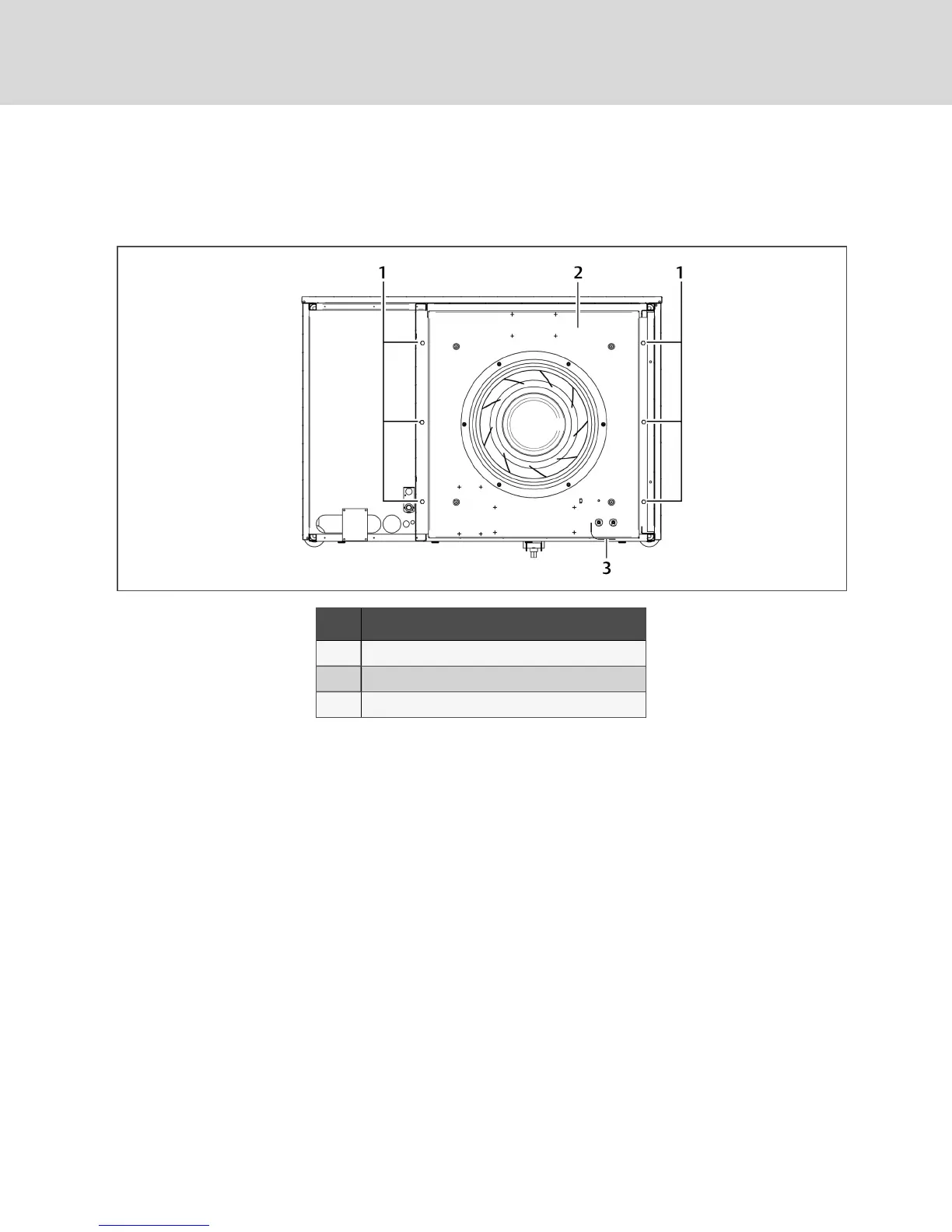
4. Remove hardware, Figure 10.5 below, that retains the fan in the lowered position, and save it
forre-installation.
NOTE: Hardware quantity and location varies depending on the type of unit.
Figure 10.5 Hardware removal
Item Description
1 1/2-in. (13-mm) Hex-head bolts (typical both sides)
2 Fan deck
3 Wiring loop
5. Use the jack to raise the fan module slowly until the fan motor clears the front frame channel.
6. Insert a field-supplied fan-removal device securely on the front and rear frame channels under
the fan module as shown in Figure 10.6 on the facing page.
• A suitable fan-removal device is two lengths of rigid material that is 4 inches (100mm)
wide and strong enough to support the weight of the fan module.
Vertiv | Liebert® DSE™ Installer/User Guide
62