REV : 10
REV DATE : 5/18
DPN002324
Page :1 /1
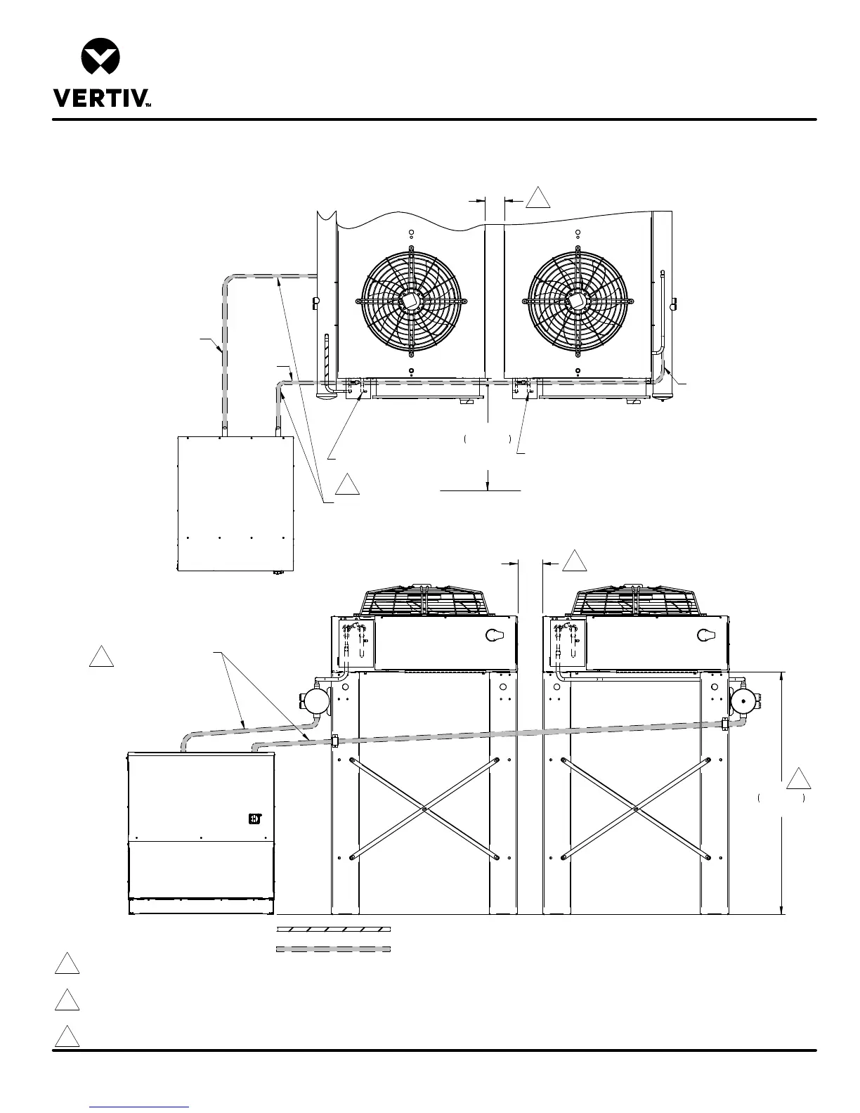
CONDENSER AND DUAL CIRCUIT ECONOPHASE UNIT
Form No.: DPN001040_REV4
UNIT ARRANGEMENT DIAGRAM
LIEBERT ECONOPHASE
CIRCUIT 2
CIRCUIT 1
60"
1524mm
Typ.
Liquid from Condenser
1-3/8" (PR085-PR125)
1-5/8" (PR250).
DO NOT TRAP LINE!
Slope (2 in. per 10 ft.) down
towards EconoPhase unit.
EconoPhase Unit
Air Cooled Condenser
Air Cooled Condenser
42"
1067mm
Minimum
Clearance
Liquid from Condenser
1-3/8" (PR085-PR125)
1-5/8" (PR250).
DO NOT TRAP LINE!
Slope (2 in. per 10 ft.) down towards
EconoPhase unit.
Entering Hot Gas Line
Entering Hot Gas Line
CIRCUIT 1
CIRCUIT 2
LIQUID LINE
TO ECONOPHASE
UNIT FROM BOTTOM
OF RECEIVER
CIRCUIT 1
CIRCUIT 2
TOP VIEW
TOP VIEW
Notes:
1. For proper pump function, a minimum elevation difference of 60” (1524 mm) must be maintained between the bottom of condenser box to the bottom of EconoPhase unit.
2. All indoor and outdoor field refrigerant piping must be insulated, 1/2" minimum. All outdoor insulation must be UV and ozone resistant.
3. Components are not supplied by Liebert but are required for proper circuit operation and maintenance.
4. For Piping Elevation refer to DPN003994.
5. Liebert MC Condenser with legs taller than 18" (457mm) require a minimum spacing of 6" (152mm) for leg bracing.
FIELD PIPING
FACTORY SUPPLIED, FIELD INSTALLED
3
3
1
5
5