Vertiv
™
|Liebert
®
MBSM
™
User Manual | 24
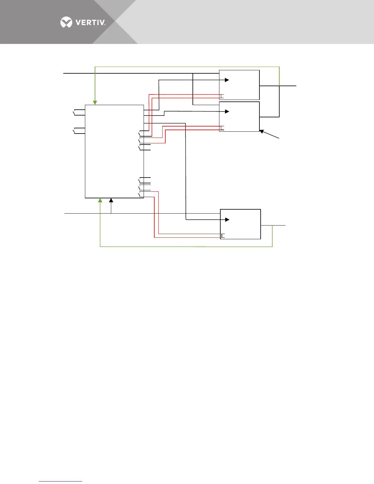
Figure 16 Liebert MBSM Interconnections to Liebert NX Dual Bus system
Figures 15 and 16 are examples of a dual-bus system composed of a modular parallel on Bus A
and a single unit on Bus B.
4.3 Power Interconnections
The Liebert MBSM is powered by the two main buses and from the two critical buses (UPS
outputs).
Main Bus A is a three phase +N line from the Transformer Box Reference Output (as shown in
2.6.1 - Transformer Box Connections) to be interconnected to the Liebert MBSM XT1 terminals
1[a], 2[b], 3[c] and 4[N]. The phase sequence MUST be the same of the UPS A reserve input.
Suggested wire size is 14AWG, protected with 10A Class CC fuse.
Main Bus B is a three phase +N line from the Transformer Box Reference Output (as shown in
2.6.1 - Transformer Box Connections) to be interconnected to the Liebert MBSM XT1 terminals
5[a], 6[b], 7[c] and 8[N]. The phase sequence MUST be the same of the UPS B reserve input.
Suggested wire size is 14AWG, protected with 10A Class CC fuse.
AUX supply A is a single phase line coming from the UPS A output via the Transformer Box
Control Power (as shown in 2.6.1 - Transformer Box Connections), to be interconnected to the
Liebert MBSM XT1 terminals 9[L] 10[N]. Suggested wire size is 14AWG, protected with 10A Class
CC fuse.
AUX supply B is a single phase line coming from the UPS B output via the Transformer Box
Control Power (as shown in 2.6.1 - Transformer Box Connections), to be interconnected to the
Liebert MBSM XT1 terminals 11[L] 12[N]. Suggested wire size is 14AWG, protected with 10A Class
CC fuse.
Input Line A
Force
Source B
Force
Source A
XT15
XT16
XT19
XT20
XP1
XP2
XP6
MBSM
With
Phase Control
Input Line A
Power System B
Single UPS
UPS B
Sync
BUS B
Digital Input
INHBIT UPS A1
INHBIT UPS A2
INHBIT UPS A3
INHBIT UPS B1
INHBIT UPS B2
INHBIT UPS B3
BUS A
UPS A1
Sync
Digital Input
UPS A2
Sync
Digital Input
Power System A
Two UPS’s in
Parallel Configuration
Digital Input :
NX225-600 = TB1