Vertiv
™
|Liebert
®
MBSM
™
User Manual | 4
1.0 INTRODUCTION
This device is used to maintain voltages from two separate sources in phase. This function
increases the energy availability at the output of the static transfer system, while the
synchronized sources upstream of the device are always available for transfer. It complies with all
relevant safety regulations governing information technology equipment.
The Liebert MBSM is designed to provide a frequency reference signal for up to 11 UPS modules,
depending on the model. This signal is a square wave generated by an incoming source reference
or by an internal quartz oscillator. Each UPS connected to the Liebert MBSM is able to receive the
frequency reference signal and, under particular conditions, to automatically phase lock the
inverter to this reference.
1.1 Concepts, Basic Architecture
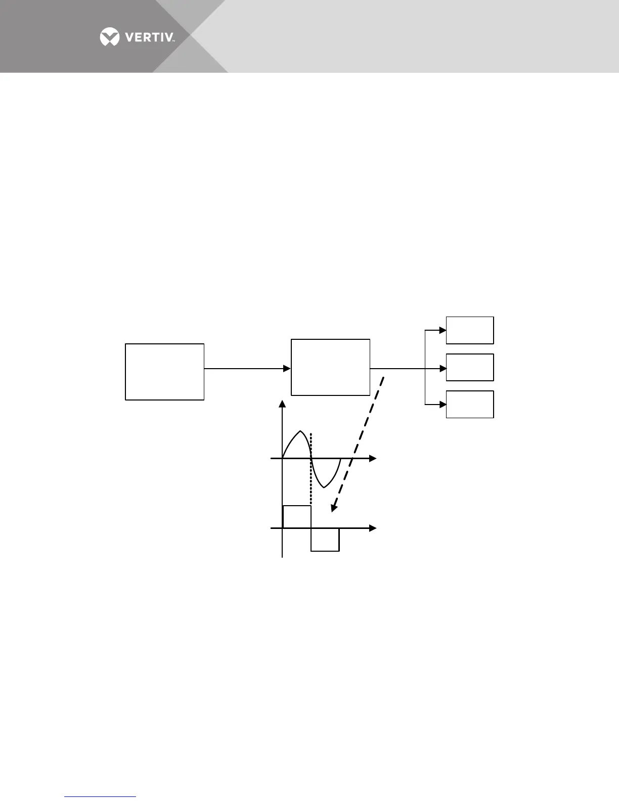
Figure 1 shows the typical block diagram of a UPS system with Liebert MBSM.
Figure 1 Block diagram of a UPS system with Liebert MBSM
Each UPS in the system is supplied by a common electrical bus; the UPS synchronization source
(reference) is the power source connected on its reserve input and, as a consequence, being the
power source common to all the UPS, the inverters outputs will be in synchronization.
When the main power (reserve inputs) fail, each UPS will synchronize the inverter to the signal
coming from the Liebert MBSM (Fref.) and, as a result, the inverters will remain synchronized.
Should the Fref. not be available (or the Liebert MBSM not be installed), each UPS will
synchronize to its own internal quartz oscillator. That would make the inverters outputs
asynchronous.
Transformer
Box
Liebert
MSBM
UPS B
UPS A
UPS C
Fr Signal
Incoming
Source = 3P+N