USER MANUAL-S600E
13
504402079908 S600E
Parallel System Features
1.
The hardware and software of a parallel system are identical to those of the individual modules. The parallel
system is configured by modifying the respective settings in the configuration software or via the control panel.
2.
Parallel cables are connected in a ring, providing both system reliability and redundancy. LBS cables are connected
between any two UPS modules of each bus. The intelligent parallel logic provides the user with maximum flexibility.
For example, the UPS modules in a parallel system can be shut down or started up in any order. Transfers between
normal mode and bypass mode of operation are seamless and self-recoverable, i.e, when the overload is cleared the
system will revert automatically to its original operating mode.
3.
The total load of the parallel system can be queried from the LCD screen on each UPS module.
Parallel System Requirements
A group of paralleled modules behave as if it were one large UPS with the advantage of providing increased
reliability. To ensure that all modules are utilised equally and to comply with relevant wiring rules, the following
requirements apply:
1.
All UPS modules must be of the same rating and must be connected to the same bypass source.
2.
The bypass and rectifier input sources must be connected to the same neutral line input terminal.
3.
If any RCD devices are installed they must be set-up appropriately and located upstream of the common neutral
line input terminal. Alternatively, the device must monitor the protective earth current of the system. Refer to
Warning: high earth leakage current before Contents.
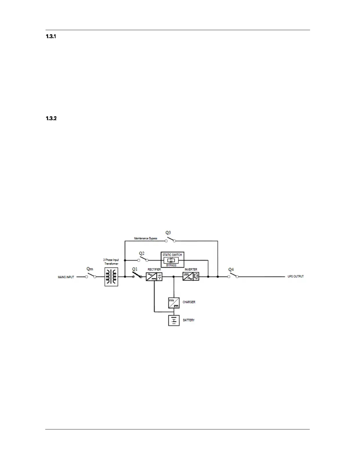
1.4
Operating Principle
The operating principle of the UPS is shown in the figure 1-4.
Figure 1.4 b (3X3 UPS with Input Transformer)
1.The UPS is composed of mains input (main and bypass), rectifier/PFC, charger, inverter, bypass, battery, DSP controller,isolation
transformer,contactor and final output.
2. When the mains is normal, the rectifier will start, and the charger will charge the battery string. Before turning on the UPS, the output
voltage is bypass voltage, and the mains supplies power to the load through the bypass. After turning on the UPS, the electronic transfer
switch connects the inverter output to the load, and the mains supplies DC power to the inverter through the rectifier/PFC circuit. The
inverter then converts DC power into pure sine wave AC power and supplies the AC power to the load through electronic transfer switch.
Isolation Transformer is connected at the at input side for 3X3 requirement. Refer figure 1.4 for the position of transformer in case of Input
Isolation .