USER MANUAL-S600E
95
S600E
10.6
Electrical Specifications (Inverter Output)
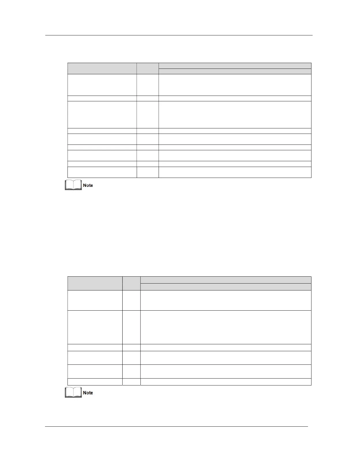
Table 10-6 Inverter output (to critical load)
Item Unit
Rated AC voltage
1
Vac
(3-in 3-out)
Overload
%
linear load requirements:
< 105%, continuous;
105 - 125% of rated load, 5min;
125 - 150% of rated load, 1min;
> 150%, 200ms
Steady state voltage stability
%
±1% for balanced three phase load;
±2% for unbalanced load
Transient voltage response
±5% for 100% rated linear load step
Total harmonic voltage
%
5% (100% non-linear load)
Rated frequency ±0.5, ±1, ±2, ±3 (settable)
Hz/s
Setting range: 0.2, 0.5, 1 (UPS module), 0.2 (parallel system)
1.
Factory set to 380V. 400V or 415V can be selected by service engineer at site.
2.
Factory set to 50Hz. 60Hz can be selected by service engineer at site. Note that the system frequency may only be changed
when the UPS is in bypass mode. It is strictly prohibited to change the system frequency when the UPS supplying the load via
the inverter.
3.
EN 50091-3 (1.4.58) crest factor 3:1, non-linear load.
4.
IEC/EN 62040-3/EN 50091-3 also for 0 - 100% - 0 load transient. Transient recovery time: returns to within 5% of steady state
output voltage within half a cycle.
10.7
Electrical Specifications (Bypass Input)
Table 10-7 Bypass input
Item Unit
10kVA-20kVA
Rated AC voltage
1
Vac
neutral reference for the output, (3-in 3-out)
Overload
%
Based on nominal voltage and rated load current under apparent power:
< 105%, continues;
105 - 125% of rated load, 10min;
125 - 150% of rated load, 1min;
> 150%, 200ms
Bypass voltage tolerance
%Vac
Upper limit: +10%, +15% or +20%, default: +20%;
Lower limit: -10%, -20%, -30% or -40%, default: -40%
tolerance
%
±5% or ±10%, default: ±10%
Rated frequency ±0.5, ±1, ±2, ±3, ±4,
±5 (settable); ±5 by default
1.
Factory set to 380V. 400V or 415V can be selected by service engineer at site.
2.
Factory set to 50Hz. 60Hz can be selected by service engineer at site.