USER MANUAL-S600E
31
S600E
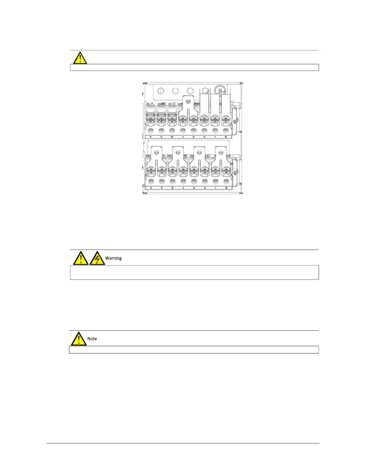
Figure 3-4 3-in 3-out, common input configuration cable connection (factory default)
Connecting the system output
In the case of 3-in 3-out configuration, connect the system output cables between the output terminals (oA-oB-oC-
oN) and the load; whereas, in the case of 3-in 1-out configurations, connect the system output cables between the
output copper shorting bars (oA-oB-oC), oN and the load. Refer to Table 3-1 for the tightening torque values. Make
sure that the phase rotation is correct.
Connecting the batteries
If the external battery is required, ensure correct polarity between the battery string terminals and the BCB, and
between the BCB and the UPS cabinet battery input terminals (Bat+, N, Bat-), i.e. (Bat+) to (+), (Bat-) to (-) and (N)
to (N).
This completes the connection procedure. At this point it is possible to replace the protective covers.
Note that the common input copper shorting bars are fitted before delivery.
terminals of the output cables are insulated safely
After connection, take appropriate measures to seal the