3. Route the input hazardous voltage electrical power wiring through the top right knockout on
the primary electrical enclosure (see Figure 3.7 on the previous page) to the disconnect
switch L1, L2 and L3 (see Figure 3.8 below). Observe proper phasing.
4. Connect the ground wire to the ground lug (see Figure 3.8 below andFigure 3.10 on the next
page for 60Hz models and Figure 3.9 below andFigure 3.11 on the next page for 50Hz models).
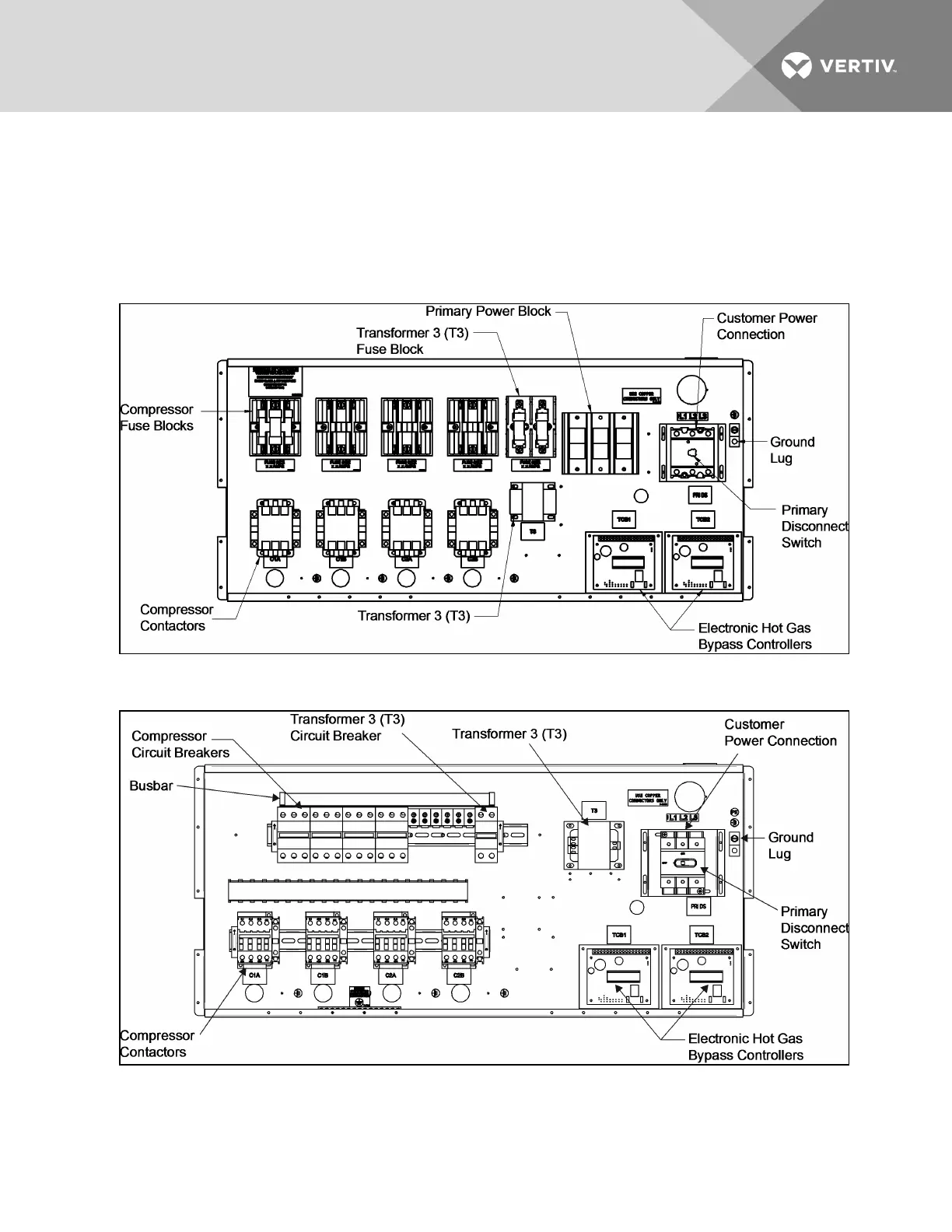
Figure 3.8 60Hz models, high voltage connections—primary disconnect switch
Figure 3.9 50Hz models high voltage connections—primary disconnect switch
Vertiv | Liebert® XDC™ User Manual | 25