LaserPLUS Product Guide VESDA
®
16
Table 5 - GPI functions
Note: The signal voltage into the GPI terminals must be between 5 to 30 VDC.
Note: When the detector is isolated or de-isolated as a GPI function, the status cannot be
changed through the normal isolate/de-isolate functions of the Display Module or
the LCD Programmer.
Note: When the night-time threshold is configured as a GPI function, it overrides the clock
settings for day-start and night-start.
When using the standby or remote isolate options it is recommended that all displays on
VESDAnet are configured to have the Isolate button disabled. When programming the display
through the LCD Programmer choose Isolate Disabled from the Button Lockout menu.
1.5 Mounting the LaserPLUS
The LaserPLUS detector can be mounted onto the wall or on any suitable secure surface using
the mounting bracket. It is strongly recommended that the detector is mounted on to the
mounting bracket included with the packaging. Determine the cable entry ports and the air
exhaust port before mounting the detector. Consideration should also be given to the positioning
of the pipe inlet ports in relation to the existing pipe network.
Caution: Press out the relevant knockouts taking care not to damage the relays and
terminals on the termination card.
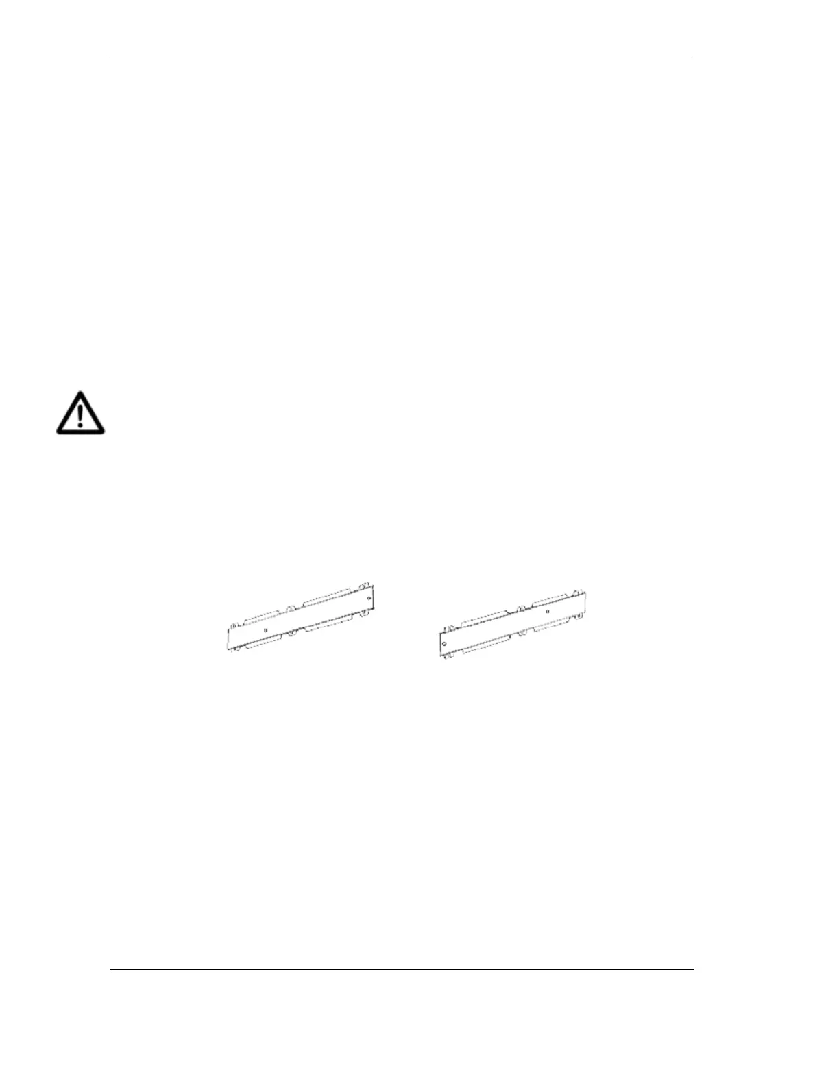
Securing the mounting bracket
The orientation required for the LaserPLUS detector will determine how the mounting bracket is
placed. To secure the mounting bracket to the mounting surface place the flat side against the
surface ensuring that the lances do not sit flush to the surface. The figure below illustrates the
bracket position for normal and inverted orientations. Secure the mounting bracket to the surface
using appropriate fasteners, ensuring that the bracket is horizontally straight and sits flush on the
surface.
Figure 10 - The mounting bracket in normal and inverted orientation