LaserPLUS Product Guide VESDA
®
20
Managing the Exhaust Air
To exhaust air from the detector, use the exhaust ports at the rear or at the bottom of the head
mounting box. Remove the appropriate exhaust port plugs and if required, connect an outlet
pipe to the exhaust manifold. In the event the side port is used as an exhaust port, press out the
knockout hole. Remove the plug on the exhaust manifold, located at the divider of the chassis
and the termination card. Run a 25 mm (1 inch) pipe through the side port and insert into the
exhaust manifold, ensuring it is a tight fit.
Note: DO NOT glue this pipe to the exhaust manifold.
Note: Some applications may require the air exhausted from the detector to be returned to
the sampling area.
1.7 LaserPLUS Wiring Connections
The Termination Card
The termination card acts as the interface for VESDAnet, power supply, relays and the General
Purpose Input (GPI).
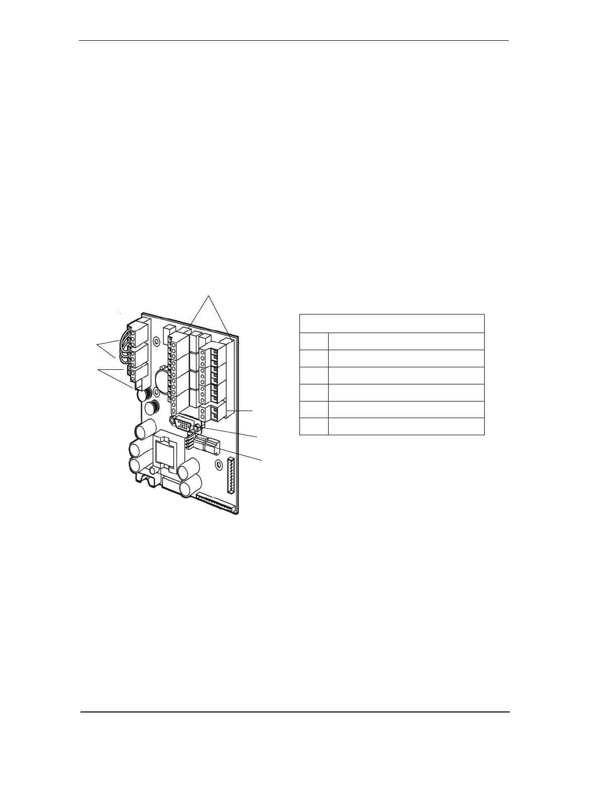
Figure 16 - Terminal card illustrating relays and termination points
VESDAnet Terminals
VESDAnet is a bidirectional data communication network between connected VESDA devices.
VESDAnet cables are terminated at the VESDAnet A and B Terminals on the termination card.
Communication wires from another VESDA device are brought into the detector at one terminal
and looped out to another device on VESDAnet from the other terminal. It is necessary to
maintain the polarity throughout the network. It is recommended that RS 485 (Belden 9841 - 120
Ohm) twisted pair cables, or similar cables be used.
Legend
A VESDAnet Terminals
B Power Terminals
C Relay Terminals
D GPI Terminal
E VESDAnet Socket
F FOK LED Connectors
A
B
D
E
F