LaserPLUS Product Guide VESDA
®
28
Replacing the chassis/Air Inlet Pipe Manifold
1. Isolate unit by pressing the Isolate button on the zone configured display or by selecting
Isolate Zone from the Zone menu in VConfig Pro or VSM3. This isolates the outputs from
the unit to a Fire Alarm Control Panel.
2. Save node configuration by using VConfig Pro or VSM3, highlight the detector in the Device
Tree Window and select Save Node Configuration from the Device menu.
3. Remove power by disconnecting the power cables.
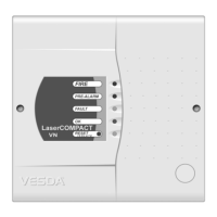
4. Remove the front panel by first opening the cover plate and screw covers, then unscrew the
front cover.
Figure 23 - Removing front cover
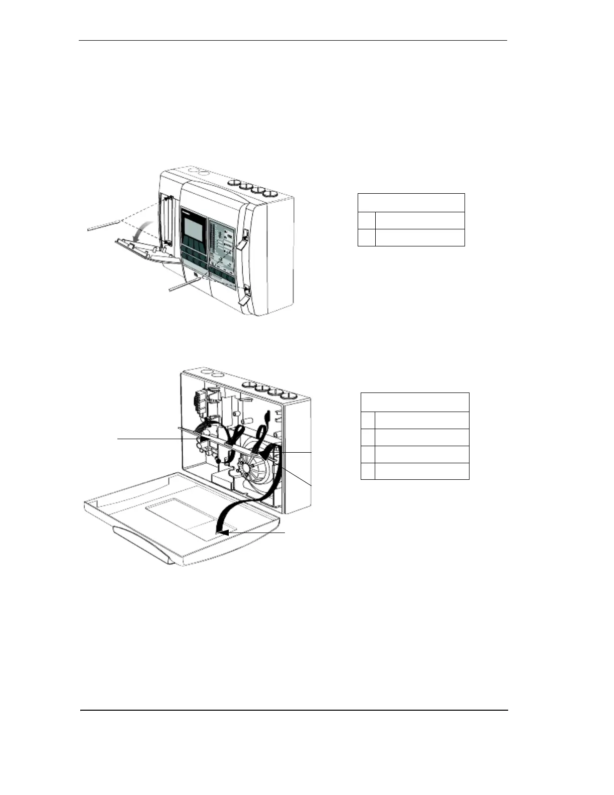
5. Disconnect data cables connecting the chassis assembly to the termination card, front
panel modules (if fitted) and manifold.
Figure 24 - Remove data cables
6. Unscrew the three manifold retaining screws
7. Remove chassis, holding the chassis by the aspirator assembly. Release the two lower
locking tabs by lifting the chassis upward and pulling outward. Use a screwdriver to assist
with tab release.
A
B
Legend
A Cover plate screws
B Screw covers
Legend
C Termination cable
D Head processor card
E Flow sensor cable
F Scanner cable
C
D
E
F