VESDA
®
LaserPLUS Product Guide
29
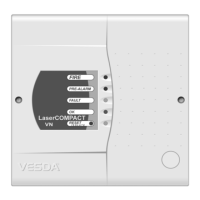
Figure 25 - Remove the chassis
Caution: Care must be taken not to damage the cable running to the manifold.
Note: The chassis consists of the Detection Chamber, head processor card and flow
sensors. These are factory calibrated as a matched set and must not be separated.
Separating the set and replacing it with components from another LaserSCANNER
will cause the detector to malfunction. This will require the chassis to be returned to
the factory.
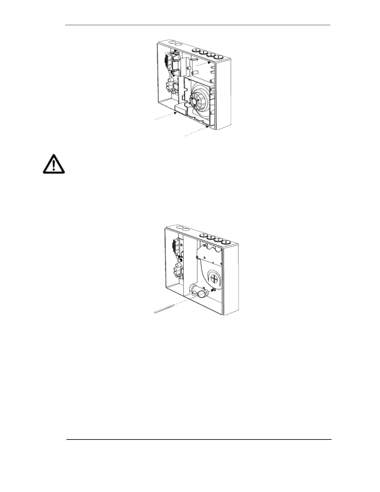
8. Disconnect the flow sensor lead.
9. Unscrew manifold retaining screws.
Figure 26 - Removing pipe inlet manifold
10. Remove the manifold by sliding it downward, away from the pipe network.
11. Attach the replacement manifold and chassis by reversing the procedure above.
12. Configure the node using VConfig PRO or VSM3 by highlighting the detector in the Device
Tree window and highlighting ‘Restore Node Configuration’ from the device menu, or
reprogram the detector using the LCD Programmer.
Note: Data cables must be plugged and unplugged only after power has been removed.
Ensure all connectors are seated correctly before applying power to unit. Failure to
observe this requirement may cause data corruption that requires factory re-
calibration.