Battery recharge circuit
The charging circuit consists of three-phase alternator and a permanent magneto flywheel.
The alternator is directly connected to the voltage regulator.
This, in its turn, is connected directly to the ground and the battery's positive terminal passing through
the 20A protective fuse.
The three-phase alternator provides good recharge power and at low revs a good compromise is ach-
ieved between generated power and idle stability.
Stator check
Checking the stator windings
WARNING
THIS CHECK-UP CAN BE MADE WITH THE STATOR PROPERLY INSTALLED.
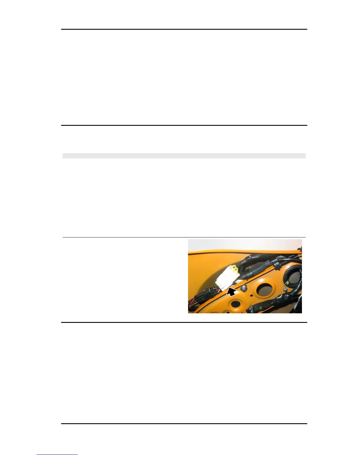
1) Lift the saddle and remove the helmet compartment.
2) Disconnect the connector between stator and regulator with the three yellow cables as shown in the
picture.
3) Measure the resistance between each of the yellow terminals and the other two.
Electric characteristic
Resistance:
0.2 - 1 Ω
4) Check that there is insulation between the each
yellow cable and the ground.
5) If values are incorrect, replace the stator.
Recharge system voltage check
Look for any leakage
1) Access the battery by removing the specific cover.
2) Check that the battery does not show signs of losing fluid before checking the output voltage.
3) Turn the ignition key to position OFF, connect the terminals of the tester between the negative pole
(-) of the battery and the black cable and only then disconnect the black cable from the negative pole
(-) of the battery.
4) With the ignition key always at OFF, the reading indicated by the ammeter must be ≤ 0.5 mA.
Charging current check
Vespa LX - S 125 3V ie 150 3V ie (2012) Electrical system
ELE SYS - 83
 Loading...