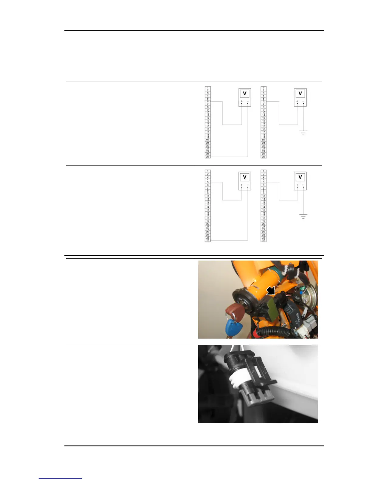
Remove the connector mounting bracket shown in
the photograph and disconnect the connector from
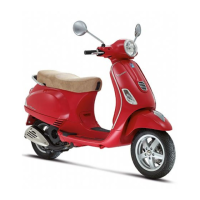
the control unit. Check the following conditions:
With the key switch set to OFF:
• there is battery voltage between terminals 6-26
and terminal 6-chassis ground (fixed power sup-
ply). If there is no voltage check that fuse 3 and its
cable are in working order.
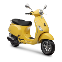
With the key switch set to ON:
• there is battery voltage between terminals 5-26
and terminal 5-chassis ground (fixed power sup-
ply). If there is no voltage, check the key switch
contacts, that fuse 2 and its cable are in working
order.
After removing the shield back plate, remove the
electrical connection from the aerial as shown in
the picture.
Remove the protective base from the connector.
Vespa LX 125 - 150 i.e. Electrical system
ELE SYS - 67
 Loading...