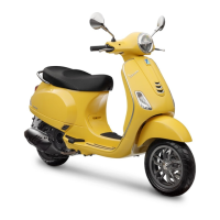
FUEL PUMP CONNECTOR
1. Not connected
2. Ground (Black)
3. Not connected
4. Not connected
5.Power supply via solenoid (Black-Green)
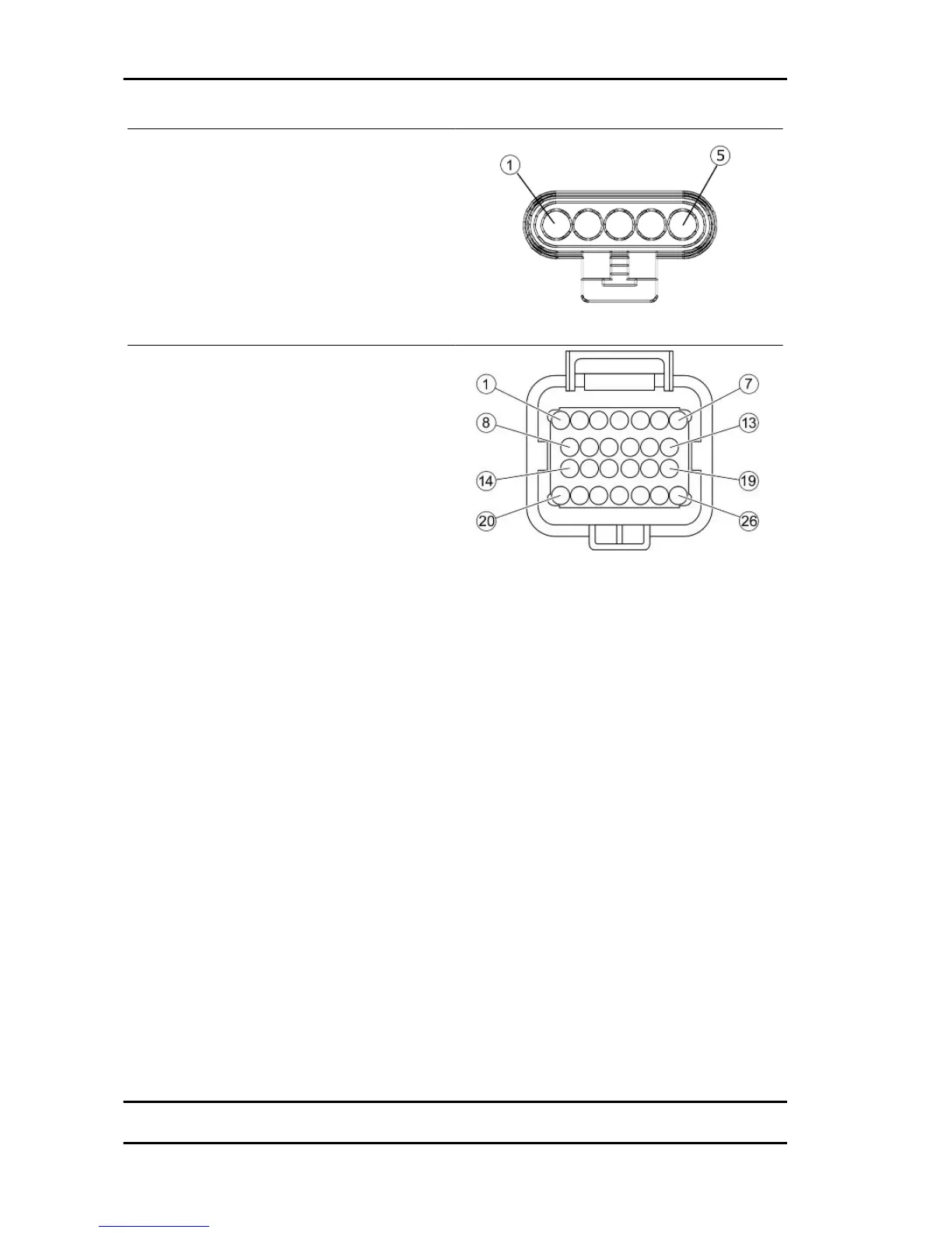
ELECTRONIC CONTROL UNIT CONNECTOR
1. Injection telltale light (Brown-Black)
2. Not connected
3. Not connected
4. Lambda probe negative terminal (White-Green)
5. Live supply (Red-White)
6. Battery powered (Grey-Black)
7. Immobilizer Aerial (Orange-White)
8. Not connected
9. Engine temperature sensor (Sky blue-Green)
10. Not connected
11. Lambda probe positive (Sky blue-Black)
12. Not connected
13. Engine speed sensor positive (Red)
14. Injector (Red-Yellow)
15. Engine speed sensor negative (Brown)
16. Diagnosis (Purple-White)
17. Immobilizer warning light (Red-Green)
18. To ground (Grey-Green)
19. Low-beam lights automatic ignition (White-
Black)
20. Injection load remote control (Black-Purple)
21. Lambda probe (Green - Yellow)
22. HV coil (Pink-Black)
23. Not connected
24. Start-up enabling (Orange-Blue)
25. Not connected
26. Ground lead (Black)
Electrical system Vespa LX 125 - 150 i.e.
ELE SYS - 82
 Loading...