8.1 CONTROL UNIT
To access the main board it is necessary to:
1 Remove the left side panel, disconnecting
the lights.
2 Remove the screw that holds the door
closed using a Phillips screwdriver.
3 Loosen the two top and bottom screws with
a screwdriver and remove the cover.
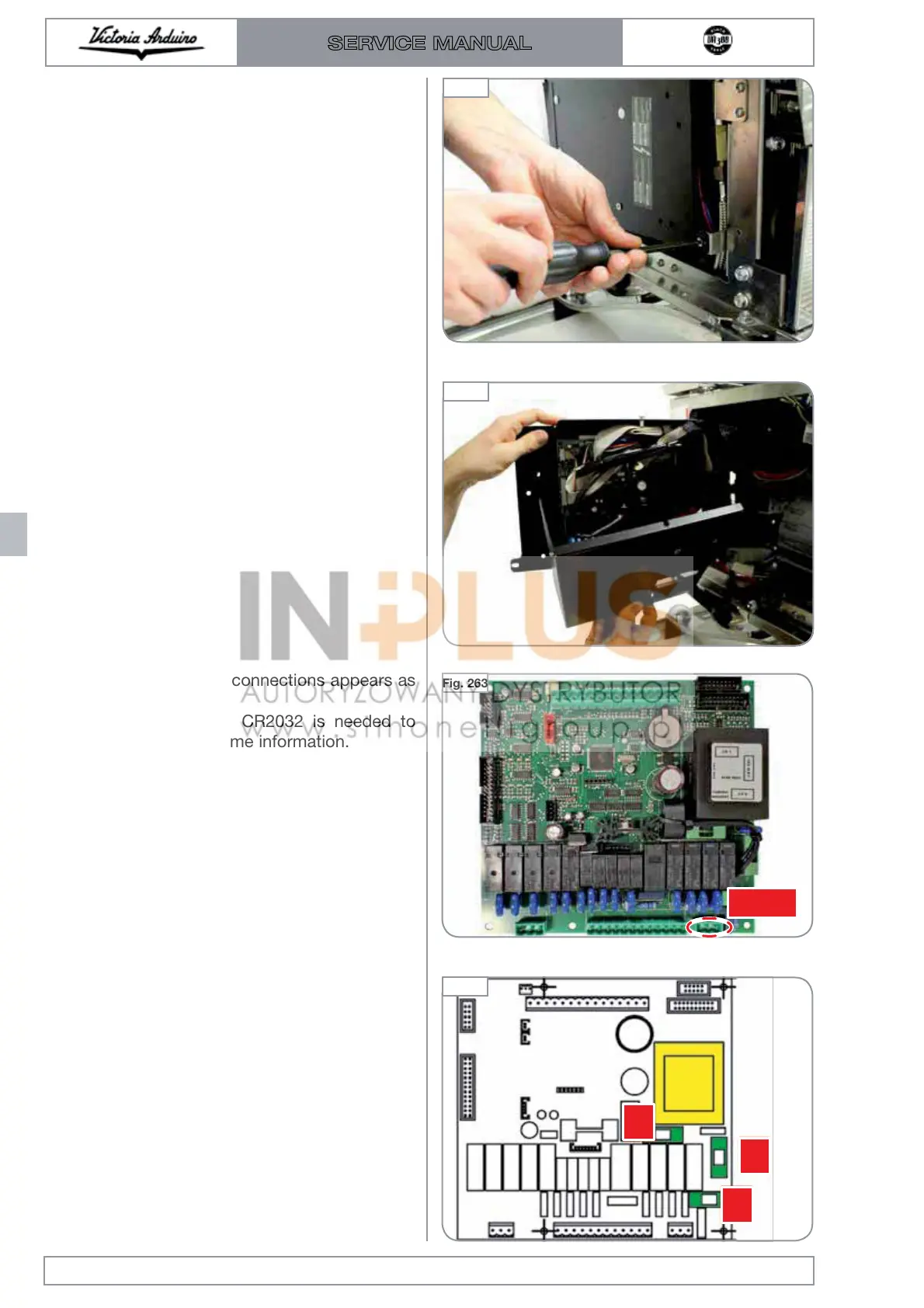
The control unit without connections appears as
shown in the figure.
The 3 volt battery type CR2032 is needed to
store meter and date / time information.
Analysing the various parts.
The transformer and fuses are located on the
right side. The fuses are:
1 5 Ampere: relay fuse.
2 1 Ampere: fuse downstream of the trans-
former (abnormal absorption on the second-
ary of the transformer).
3 160 mAmpere: transformer input fuse.
Edition 01 of 08/2017
8.2
SERVICE MANUAL
Fig. 261
Fig. 262
Fig. 263
Fig. 264
IN 220V

 Loading...