8.8
REPLACEMENT OF GROUP
PUSH BUTTON PANELS AND
SCREENS
1 Remove group bodies as shown in detail in
Chapter 3
2 Disconnect the cable connected to the
screen and the one connected to the panel.
The keyboards of the various groups are all con-
nected to the same ribbon cable. Each group
then has a unique address which is set using DIP
switches.
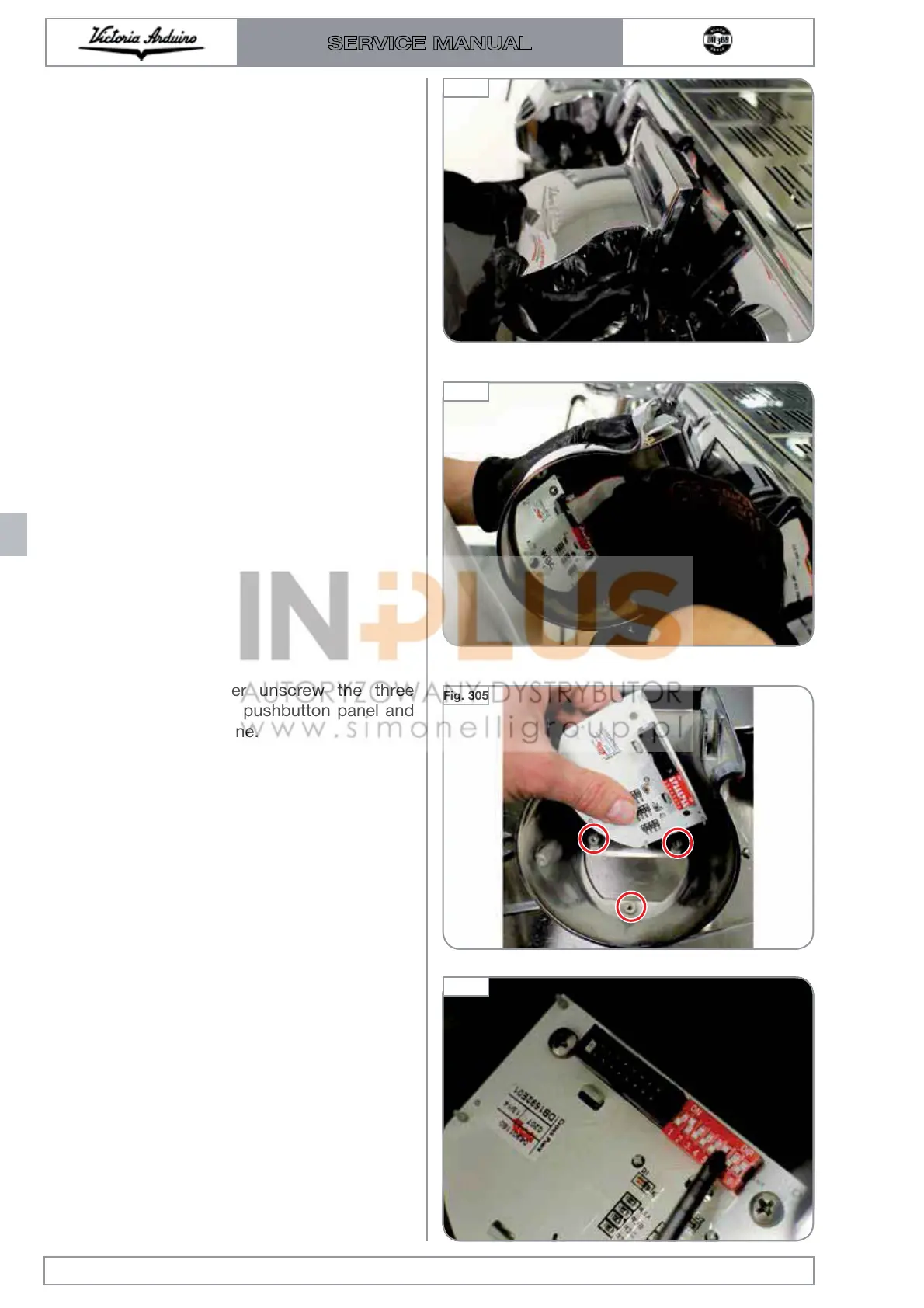
3 Using a screwdriver unscrew the three
screws that hold the pushbutton panel and
replace with a new one.
When a block is replaced it is necessary to reset
the pins with the same configuration.
In keyboards there are 8 Pins that must be con-
figured as follows:
GROUP 1 (left) pin 1-5 ON
GROUP 2 (left) pin 2-6 ON
GROUP 3 (left) pin 3-7 ON
The picture shows the configuration of group 2.
Edition 01 of 08/2017
8.16
SERVICE MANUAL
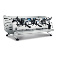
Fig. 303
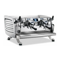
Fig. 304
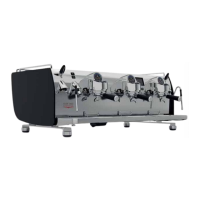
Fig. 305
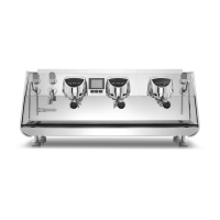
Fig. 306

 Loading...