45
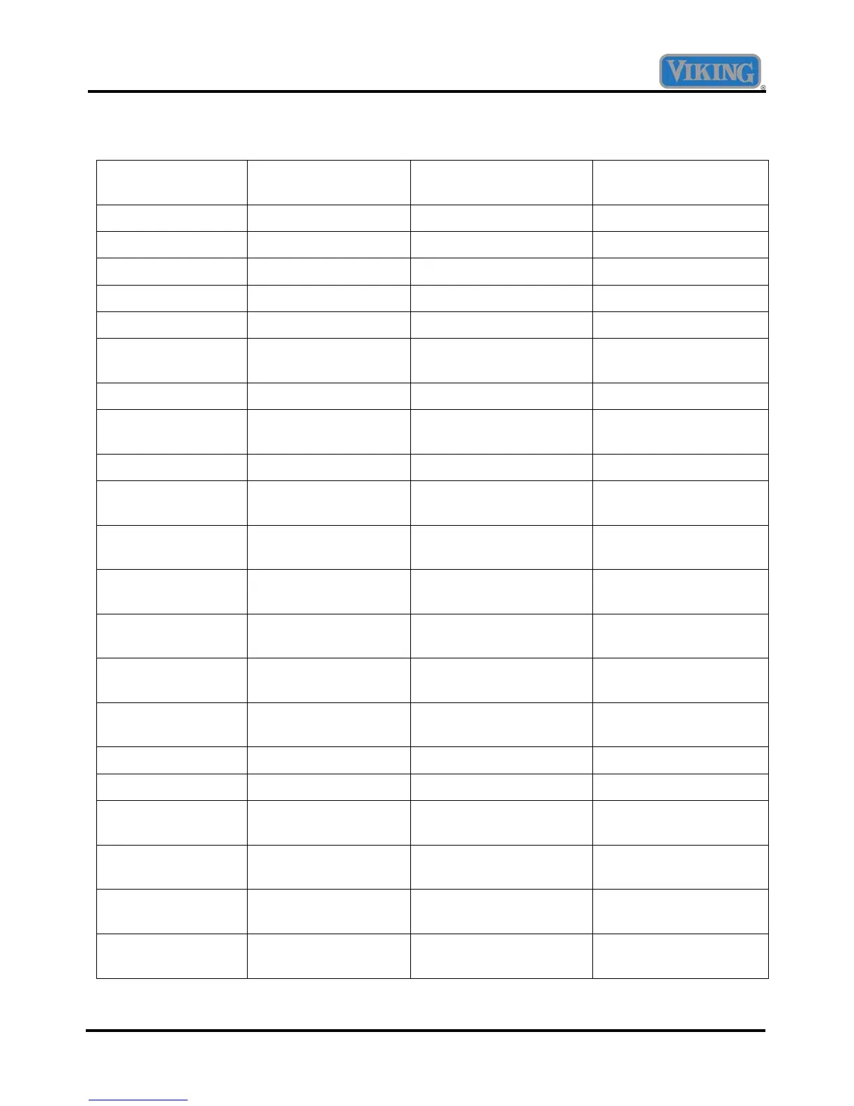
Component Testing
Component Operating Voltage
(approximate)
Resistance
(approximate)
Test Location
Convection Element 240 VAC 18.2 Ohms K17 yellow – P2 white
Outer Broil Element 240 VAC 30.2 Ohms K17 yellow – P6 grey
Inner Broil Element 240 VAC 34.0 Ohms K17 yellow – P6 purple
Outer Bake Element 240 VAC 37.2 Ohms K17 yellow – P5 blue
Inner Bake Element 240 VAC 37.8 Ohms K17 yellow – P5 orange
RTD (Resistive
Thermal Device)
5 VDC 1100 Ohms @ 75°F (See
chart for more options)
P15 pin 1 – pin 2
Convection Motor 240 VAC 100 Ohms L2- P4 blue, L2 – P4 grey
Blower Motor(s) 120 VAC 18.2 Ohms single oven
9.3 Ohms double ovens
N– P11 white
Door Latch Motor 240 VAC 12.86K Ohms L2 – P12 white
Door Latch Switch –
door unlocked
5 VDC Open P19 green – orange
Door Latch Switch –
door unlocked
0 VDC Closed P19 green – blue
Door Latch Switch –
door locked
0 VDC Closed P19 green – orange
Door Latch Switch –
door locked
5 VDC Open P19 green – blue
Thermal Cut-Out –
open contacts
240 VAC Open L2 – P1 black
Thermal Cut-Out –
closed contacts
0 VDC 0 Ohms L2 – P1 black
Cycle Light 240 VAC Open (neon light) L2 – P12 grey
Clean Light 240 VAC Open (neon light) L2 – P12 purple
Oven Light Switch –
off (door closed)
16.3 VDC Open (P20 brown – grey) P20 grey – purple
Oven Light Switch –
on (door closed)
0 VDC 0 Ohms (P20 brown –
grey)
P20 grey – purple
Oven Door Switch –
(door closed)
0 VDC 0 Ohms (P20 brown –
purple)
P20 brown – purple
Oven Door Switch –
(door opened)
15.5 VDC 0 Ohms (P20 brown –
purple)
P20 brown – purple
 Loading...