Here the interrupts, the counter function should trigger, may be
selected. You have the following options:
n None: There is no interrupt triggered.
n Process: The counter component triggers a hardware interrupt.
n Diagnostics and Process: With the CPU the diagnostic interrupt of
the digital in-/output periphery is only supported in connection with
"hardware interrupt lost".
There are no interrupts with the pulse width function.
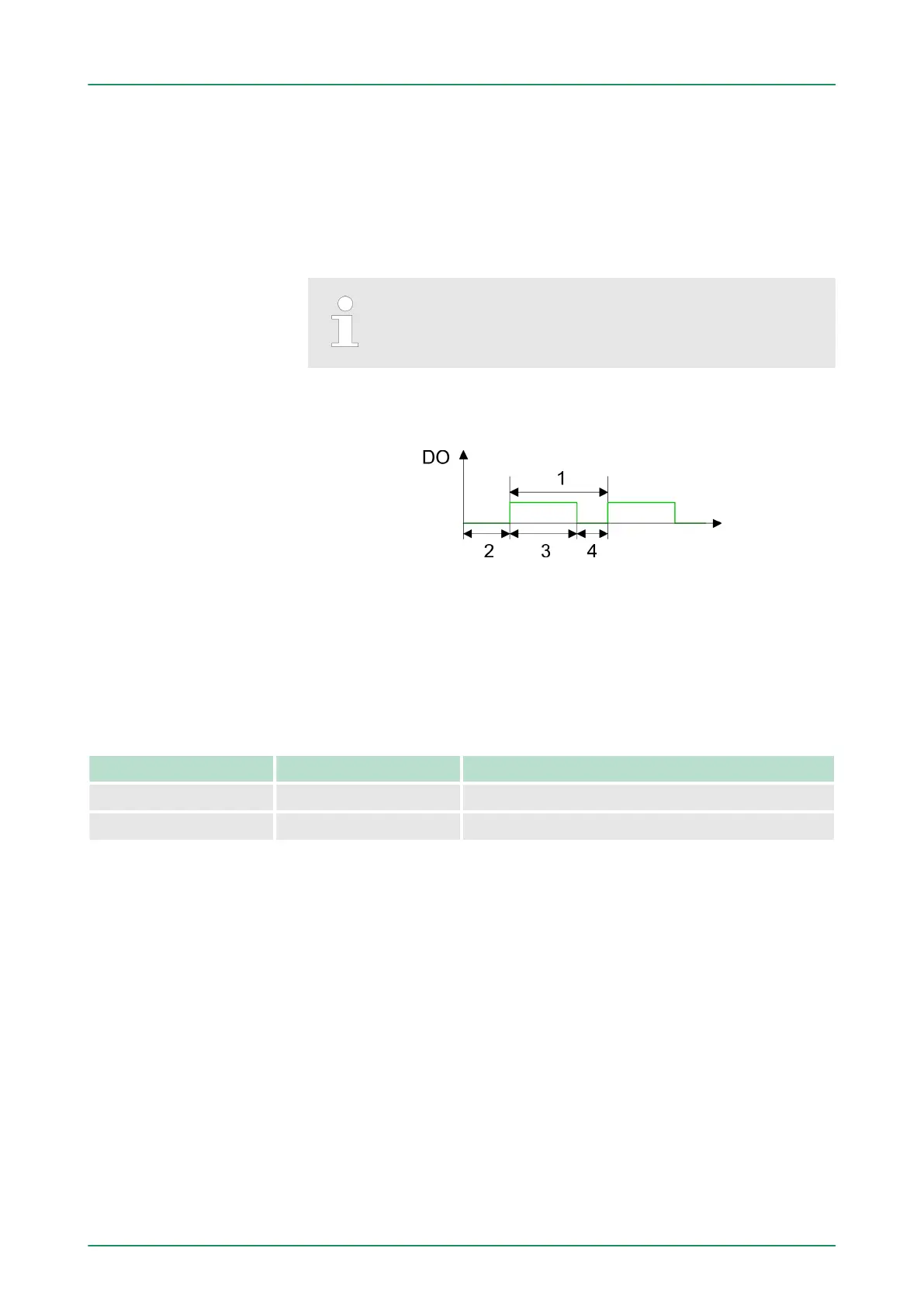
The following parameters are relevant for pulse width modulation.
Parameters, which are not listed here, are ignored by the CPU.
1 Period duration
2 ON delay
3 Pulse duration
4 Pulse pause
Output format
n Here select the range of values of the output value. With this the
CPU calculates the pulse duration:
Output format Range of values Pulse duration
Per mil (Default) 0 ... 1000 (Output value / 1000) x Period duration
S7 analog value 0 ... 27648 (Output value / 27648) x Period duration
Time base
n Set the time base, which is valid for resolution and the range of
values of period duration, minimum pulse duration and on-delay.
n If you have checked the "1ms" button times with a resolution of
1ms can be set.
n If you have checked the "0.1ms" button times with a resolution of
0.1ms can be set.
n Default: "0.1 ms"
On-delay
n Enter a value for the delay time between the start of an output
sequence and the output of the pulse. The pulse sequence is
output on the output channel after the on-delay has expired.
n Range of values: 0 ... 65535ms respectively 0 ... 6553.5ms
Basic parameters
Pulse width modulation
VIPA System 300SDeployment I/O periphery
Pulse width modulation - PWM > Parameterization
HB140 | CPU-SC | 312-5BE13 | GB | 15-50 128