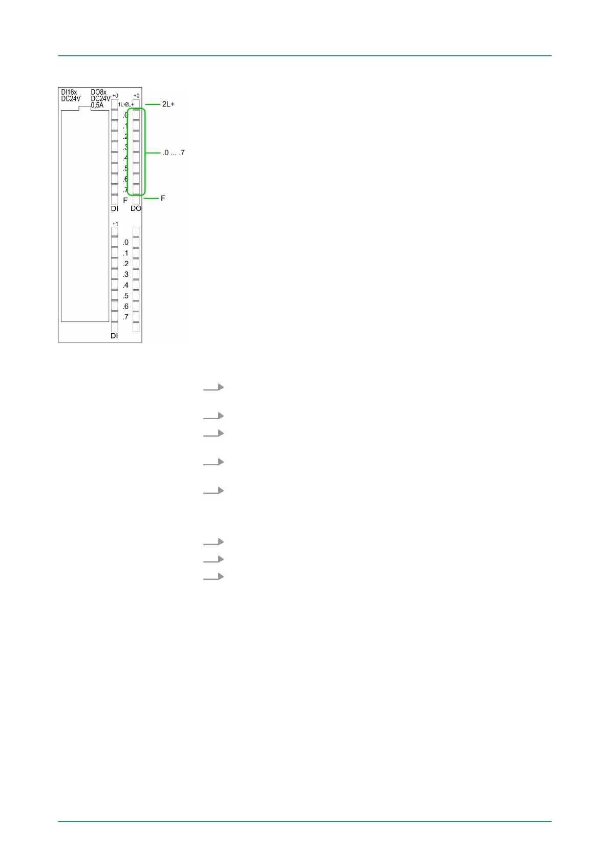
Status indication X11: DO
n 2L+
–
LED (green)
Supply voltage available for DO
n .0 ... .7
– LEDs (green)
Q+0.0 ... Q+0.7
The according LED is on at active output
n F
– LED (red)
Overload or short circuit error
6.7.2 Parameterization
1. Start the Siemens SIMATIC Manager with your project and open
the hardware configurator.
2. Place a profile rail.
3. Configure at slot 2 the Siemens CPU 312C (6ES7
312-5BE03-0AB0 V2.6).
4. Open the dialog window "Properties" by a double click to the
Count submodule of the CPU.
5. As soon as you select the operating mode "Pulse width modula-
tion" to the corresponding channel, a dialog window for the pulse
width modulation is created and displayed and filled with default
parameters.
6. Execute the wished parameterization.
7.
Save the project with ‘Station è Save and compile
’.
8. Transfer the project to the CPU.
6.7.2.1
Parameter overview
In the following the parameters are listed which may be used for
pulse width modulation configuration during hardware configuration.
Parameters, which are not listed here, are ignored by the CPU.
Here the short description of the counter function may be found. At
Comment information about the module such as purpose may be
entered.
Here the start address of the counter function is set.
General
Addresses
VIPA System 300S Deployment I/O periphery
Pulse width modulation - PWM > Parameterization
HB140 | CPU-SC | 312-5BE13 | GB | 15-50 127