open (activate): In the user program by setting SW_GATE
of SFB 48
close (deactivate): In the user program by resetting SW_GATE of
SFB 48
6.7 Pulse width modulation - PWM
6.7.1 Overview
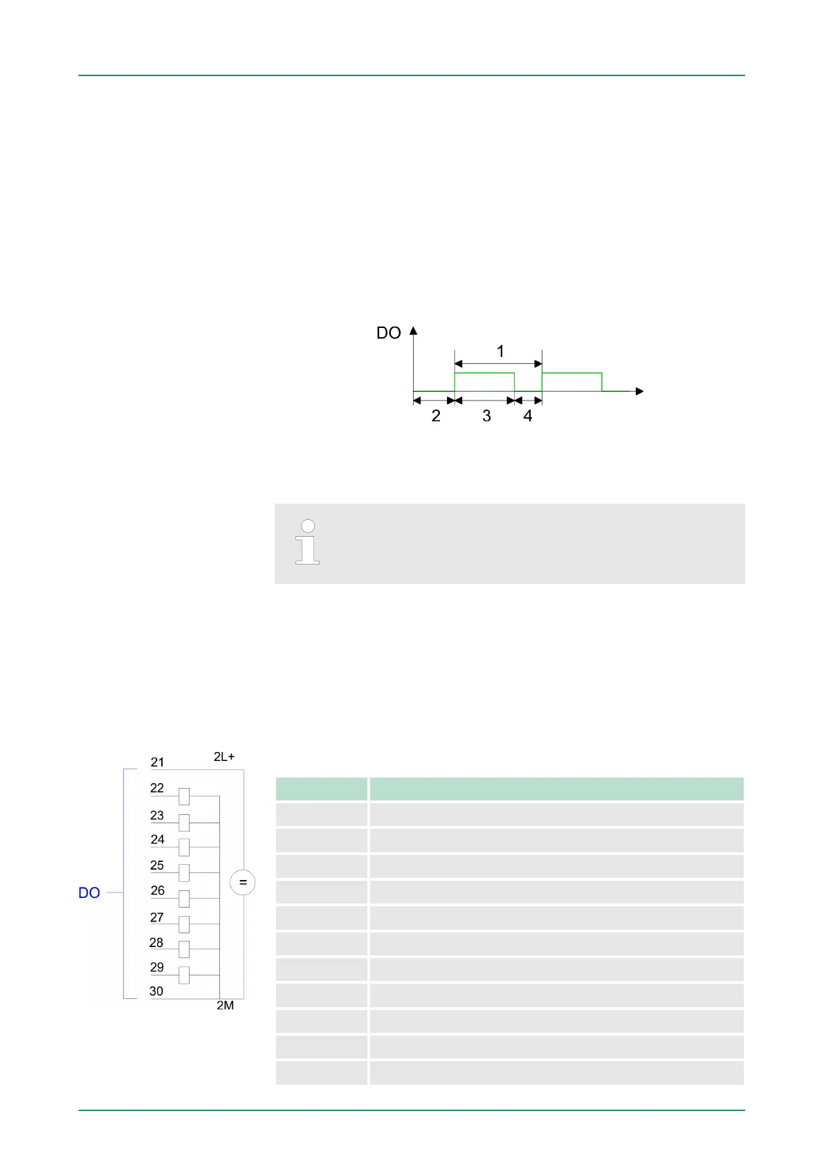
With the pulse width modulation (PWM) by presetting of time parame-
ters the CPU evaluates a pulse sequence with according pulse/break
ratio and issues it via the according output channel.
1 Period duration
2 ON delay
3 Pulse duration
4 Pulse pause
During pulse width modulation the count function at the
same channel is deactivated.
For pulse width modulation connect your actuators to the following
pins:
Channel 0: Pin 22
Channel 1: Pin 23
Connect the common ground to pin 30.
Pin assignment X11: DO
Pin Assignment
21 2L+ Power supply +DC 24V
22 O+0.0 / Channel 0 Output
23 O+0.1 / Channel 1 Output
24 Q+0.2
25 Q+0.3
26 Q+0.4
27 Q+0.5
28 Q+0.6
29 Q+0.7
30 Ground 2M DO
31 ... 40 not used
PWM
PWM Outputs
VIPA System 300SDeployment I/O periphery
Pulse width modulation - PWM > Overview
HB140 | CPU-SC | 312-5BE13 | GB | 15-50 126