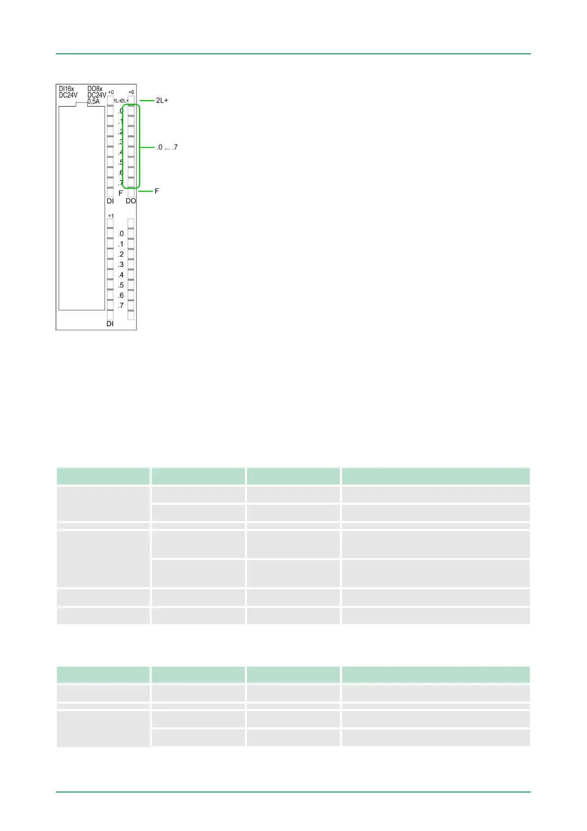
Status indication X11: DO
n 2L+
–
LED (green)
Supply voltage available for DO
n .0 ... .7
– LEDs (green)
Q+0.0 ... Q+0.7
The according LED is on at active output
n F
– LED (red)
Overload or short circuit error
6.4.1 Access to the I/O area
The 312-5BE13 creates in its peripheral area an area for input
respectively output data. Without a hardware configuration the in the
following specified default addresses are used.
6.4.1.1 Address assignment
Sub module Default address Access Assignment
DI10/DO6 124 Byte Digital Input I+0.0 ... I+0.7
125 Byte Digital Input I+1.0 ... I+1.7
Counter 768 DInt Channel 0: Count value / Frequency
value
772 DInt Channel 1: Count value / Frequency
value
776 DInt reserved
780 DInt reserved
Sub module Default address Access Assignment
DI10/DO6 124 Byte Digital Output Q+0.0 ... Q+0.7
Counter 768 DWort reserved
772 DWort reserved
Input range
Output range
VIPA System 300S Deployment I/O periphery
Digital part > Access to the I/O area
HB140 | CPU-SC | 312-5BE13 | GB | 15-50 97