USER MANUAL
15
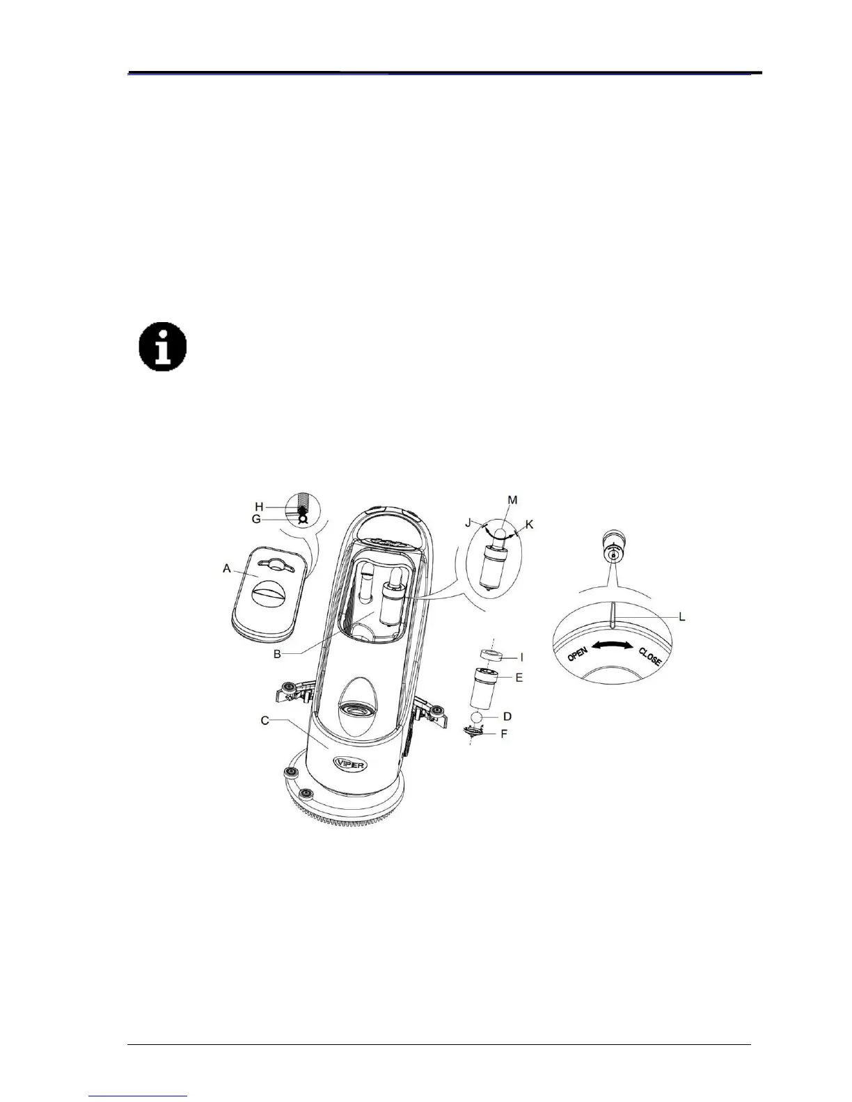
WATER TANK AND FLOAT FILTER MESH CLEANING
1. Move the machine to a dedicated draining area.
2. Press the power switch (41) to the position “O” to turn off the machine.
3. Open recovery tank lid (A, Figure 16), and remove the float device (36) from inside the tank.
4. Use clean water to rinse the recovery tank lid (A), the tank (B and C), and the float filter support
frame (E). Drain all the water from the water tank.
5. If necessary, following the symbols “Open” and “Close” as shown in Figure 16, open the bottom
lid (F) of the float filter and clean the float (D), float filter support frame (E), and the filter sponge
(I). After cleaning, re-attach the float onto the support frame (E), and then align the mark groove
(L) of the bottom lid (F) of the float filter with the mark groove (L) of the float filter support frame
(E). Turn the bottom lid (F) of the float filter tight, and re-attach the filter sponge (I) onto the
support frame (E), and then onto the vacuum tube (M).
6. Inspect the seal / gasket (G) of the recovery tank lid.
NOTE
The seal / gasket (G) of the recovery tank allows the tank to create a vacuum. It
must be completely sealed to be able to effectively suck the wastewater from the
floor.
If necessary, If necessary, the recovery tank seal / gasket (G) may be taken out from the groove
(H) and changed. When installing the new seal / gasket as shown in Figure 16 below, install the
connector to the middle section of the rear part.
7. Check if the receiving surface of the sealing strip (G) is intact and seals adequately.
8. Close recovery tank lid (A).
Figure 16
SOLUTION FILTER CLEANING
1. Drain all the water from Solution tank as previously outlined.
2. Move the machine to a flat and smooth surface.
3. Press the power switch (41) to the “O” position to turn off the machine.
4. Turn off the draining ball valve (A, Figure 17) (located at the bottom of the machine, behind the
wheels). Position B ball valve open, and position C ball valve closed.
5. Remove the transparent cap (D), and then take off the filter (E), and install them onto the filter
box (F) after cleaning.