VM1000C Pilot’s Guide Page
23
through the firewall into the engine compartment. Allow sufficient service
loop to facilitate removal of the connectors for servicing. These wiring
harnesses are labeled as follows:
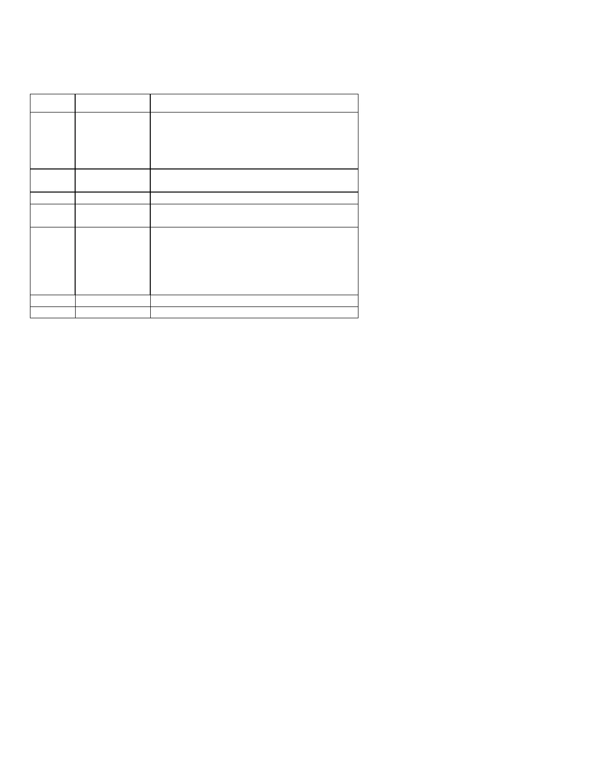
Conn Harness PN Measurements
J1 790200 Oil temperature, Induction temperature,
Carburetor temperature, Outside air
temperature, Turbine inlet temperature,
Turbine inlet temperature 2, Power, Engine
ground, MFD input, MFD output
J2 700700
700702
CHT, EGT 6 cylinder
CHT, EGT 4 cylinder
J3 790420 RPM, MAN, Oil pressure
J4 700709 Serial data to GPS, Serial data from GPS,
Fuel flow transducer
J5 700719-1 no
fuel level
700719-2
capacitive
700719-3
resistance
Fuel pressure, amperes
Fuel pressure, amperes, capacitive fuel level
option
Fuel pressure, amperes, resistive fuel level
option
J6 790745 External remote display
J7 EC100 ribbon cable connector
Route the wires from the connectors through the firewall using fireproof
rubber grommets and flame retarding silicone. Use an existing hole if
possible. All wires must be routed away from high temperature areas
(exhaust stacks, turbochargers, etc.). Secure probe and sensor leads to
a convenient location on the engine approximately 8 to 12 inches from
the probe or sensor, being sure there is sufficient slack to absorb engine
torque. It is essential in routing the probe wire that this wire not be
allowed to touch metal parts of the air-frame or engine since abrasion will
destroy this high temperature wire. Secure wires along the route to the
indicator. Secure wire using original clamps, tape or tie wrap if possible.
CAUTION: Be sure any wiring does not obstruct the control
movement under the instrument panel.
The probe wires must not be tied in with ignition, alternator or engine
cabin heater ignition wires because of potential interference with
temperature measurements.