10 D-302541
4. PROGRAMMING
4.1 INTRODUCTION
Your system is equipped with a partitioning feature (in a
PowerMax Pro Partition system) that can divide your alarm
system into three distinct areas identified as Partition 1
through 3. Partitioning can be used in installations where
shared security systems are more practical, such as a
home office or warehouse building. When partitioned, each
zone, each user code and many of your system's features
can be assigned to Partition 1 to 3.
Note: When partition is disabled, all zones, user codes, and
features of the PowerMax Pro will operate as in a regular
unit. When partition is enabled, all zones, user codes, and
features of the PowerMax Pro are automatically assigned to
Partition 1.
4.1.1 General Guidance
We recommend to program the PowerMax Pro on the work
bench before actual installation. Operating power may be
obtained from the backup battery or from the AC power supply.
The installer’s menu is accessible only to those who know
the installer’s 4-digit code, which is 9999 by factory default.
Note: Access to the installer menu, in PowerMax Pro that
has "User Permission" enabled (for example in UK) is
accessible only at the end of the user menu. This option
can be changed if necessary (see par. 4.4.36).
For PowerMax Pro that has 2 installer codes, the default
MASTER INSTALLER code is 9999 and the default
INSTALLER code is 8888.
The following actions can be done only by using the
master installer code:
• Changing master installer code.
• Resetting the PowerMax Pro parameters to the default
parameters,
• Defining specific communication parameters, as
detailed in a note in Figure 4.5.
Obviously, you are expected to use this code only once for
gaining initial access, and replace it with a secret code
known only to yourself.
You will mainly use 5 control pushbuttons during the entire
programming process:
- to move one step forward in a menu.
- to move one step backward in a menu.
-
to enter the relevant menu or confirm data.
- to move one level up in a menu.
- to return to the "OK TO EXIT" state.
The sounds you will hear while programming are:
- Single beep, heard whenever a key is pressed.
- Double beep, indicates automatic return to the
normal operating mode (by timeout).
☺
- Happy Melody (- - - –––), indicates successful
completion of an operation.
- Sad Melody (–––––), indicates a wrong move
or rejection.
4.1.2 Entering an Invalid Installer Code
If you enter an invalid installer code 5 times, the keypad
will be automatically disabled for a pre-defined period of
time and the message WRONG PASSWORD will be
displayed.
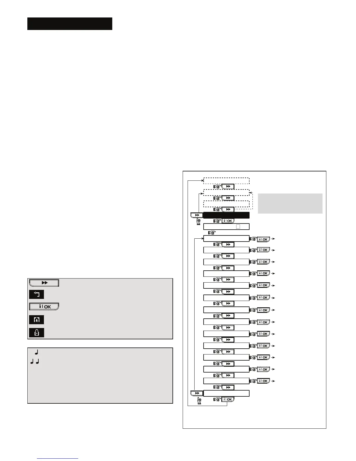
4.1.3 Installer’s Menu
The installer's menu is shown in Figure 4.1a. The text in
rectangles represents the current PowerMax Pro display.
4.1.4 Setting a New Installer Code
To set an installer code, perform the actions that are
presented in Figure 4.1b. When you are instructed to enter
code, enter a 4-digit code.
4.1.5 Setting a New Installer Code in
PowerMax Pro that has 2 Installer
Codes
For PowerMax Pro with 2 installer codes, MASTER
INSTALLER code (default 9999) and INSTALLER code
(default 8888), set new codes as shown in figure 4.1c.
For details regarding the different authorization levels
when logging in with installer code and master installer
code, refer to the note inside Figure 4.5 (DEFINE COMM).
By using the master installer code, the menu enables
changing both master installer code and installer code. By
using the installer code, the menu enables changing the
installer code only.
(See figure 4.9)
(See figure 4.3)
(See figure 4.4)
(See figure 4.5)
(See figure 4.8 )
(See chapter 7
in User Guide)
(See figure 4.2)
14. START UL/DL
13. SERIAL NUMBER
12. FACTORY DEFLT
11. USER SETTINGS
10. DIAGNOSTICS
9. DEFINE VOICE
8. DEFINE OUTPUTS
5. DEFINE COMM.
4. DEFINE PANEL
3. DEFINE ZONES
2. ENROLLING
1. NEW INSTL CODE
ENTER CODE
INSTALLER MODE
USER SETTING
WALK TEST
READY 00:00
[installer code]
(First display)
(See figure 4.10)
(See fig. 4.1b & 4.1c)
(See par. 4.12)
(Control Panel
serial number
display)
<OK> TO EXIT
(See section 4.14)
(*)
15. PARTITIONING
(See figure 4.15)
Note:
For UK panels (and versions
with USER PERMIT enable)
enter the INSTALLER MODE
via the USER SETTING menu.
(*) Applicable only when "USER PERMIT" function is enabled
(see par. 4.4.36 - USER PERMIT).
Figure 4.1a - Installer’s Menu