6 D-302541
PHONE WIRING USING TERMINAL BLOCK CONNECTORS (NORTH AMERICA)
RJ-31X
CORD
HOUSE
PHONES
RJ-31X
8-POSITION
RJ-31X PLUG
BROWN
GRAY
GRN
RED
LINE
FROM
STREET
1
23
4
5
6
7
RJ-31X JACK
GRAY
BROWN
RED
GREEN
Figure 3.1b – Phone Wiring
Phone wiring in the UK: Line terminals must be connected to pins 2 and 5 of the wall jack.
For all installations: If DSL service is present on the phone line, you must route the phone line through a DSL filter
(refer to MESSAGE TO THE INSTALLER on page 2 for further details).
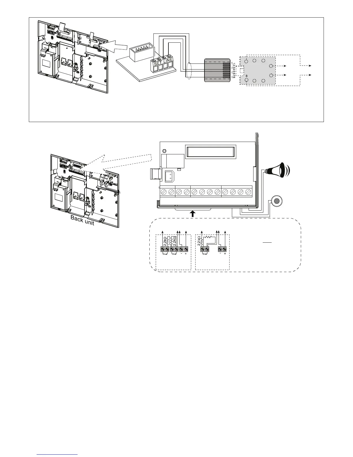
3.5.2 Zones and Sirens Wiring
Note
Regarding zones 29 & 30, the Control
Panel “sees” a specific resistance
according to the event, as follows:
Normal
(no alarm & no tamper): 2.2 k
Ω
Alarm event
: 4.4 k
Ω
Tamper event
: Infinite resistance
CONNECT WIRED DETECTORS AS FOLLOWS:
(*)
Power
ZONE 29 /
ZONE 30 GND
TAMP
N.C.
V+
(*)
Alarm
N.C.
ZONE 29 /
ZONE 30
Power
GND
2.2 k
Ω
V+
Alarm
N.C.
Detector with
Tamper switch
Detector without
Tamper switch
SRN
EXT
+12VSRN
INT
PGM+12VGNDZONE
30
GND V+ZONE
29
SITE
INTERNAL
SIREN OR
STROBE
SITE
EXTERNAL
SIREN
DC
IN -
DC
IN +
ZONES
Figure 3.1c – Zones and Sirens Wiring
Notes:
* Zone 29/GND and Zone 30/GND terminals can be
connected to a normally closed contact of a detector,
switch (for example a Tamper switch of any device), or a
pushbutton, via a 2.2 K
Ω
resistor. The 12V terminal can
be used to supply 12V (up to 36mA) to a detector
(if necessary).
** Both +12V terminals are identical (shorted together).
The EXT terminal can be used to trigger an external siren.
The INT terminal can be programmed for an "internal
siren" or "strobe" (see DEFINE OUTPUTS - DEFINE
INT/STRB in par. 4.8).
The +12V and "GND" terminals can be connected to a
siren (for constant DC power supply) – not
applicable in North America.
WARNING!
When an Internal GSM module is connected,
the CELL/PC port of the Dual RS-232 module cannot be
used for PC connection. In this case, either remove the
Internal GSM or use the PL/PC connector.
IMPORTANT! The terminals for internal and external
sirens are DC outputs intended for 12V sirens. Connecting
a loudspeaker to any of these outputs will cause a short
circuit and will damage the unit.
3.5.3 Installing an Optional X-10 Siren
If you need a “wireless” external siren, you may install an
X-10 siren module which is triggered by a signal transmitted
via the built-in electrical wiring of the protected site. This
siren can replace the regular external siren or complement
it without laying out additional wires. Of course, such a siren
can be used only in conjunction with an optional power-line
interface module.
The X-10 siren is ready to function upon connection to an
electrical power outlet, without re-programming the
PowerMax Pro. You only have to set the HOUSE CODE
and the UNIT CODE selectors on the X-10 siren as follows:
House Code: Set this selector to the letter that follows, by
alphabetical order, the letter that you programmed as a
house code for the protected premises. For example, if the
programmed house code is “J”, set the siren house code
selector to “K”.
Note: If the programmed house code letter is “P” (which is
the last programmable letter), select “A” for the siren.
Unit Code: The siren will function only if you set the unit
code selector to “1”.