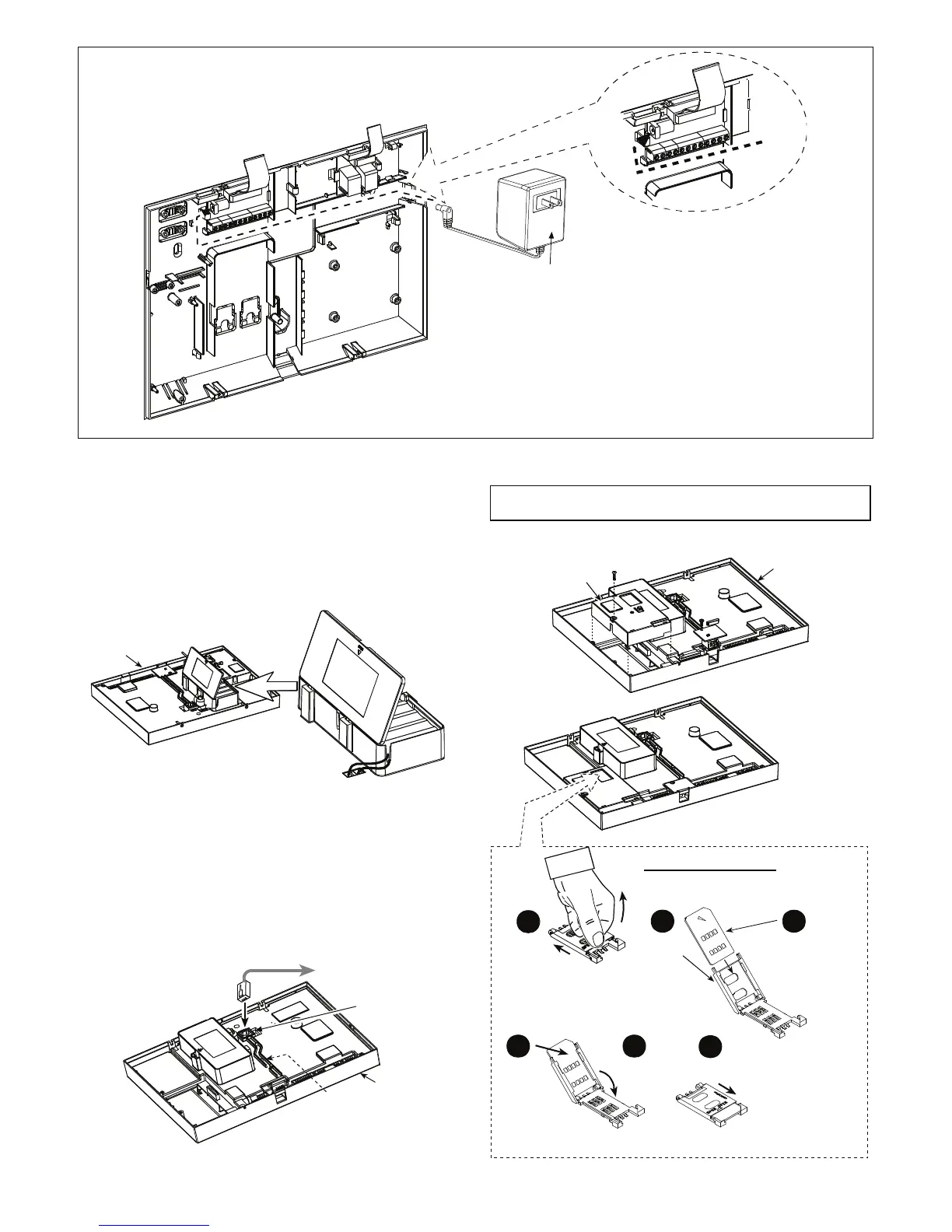
12.5VDC
100-240V
50/60Hz
Wall Mounted
Switched AC/DC
Power Supply
Figure 3.1g – Wall Mounted Switched AC/DC Power Supply Connection
3.6 Front Unit Preparation
3.6.1 Backup Battery Insertion
Open battery compartment cover (see Figure 3.1h). Insert
one 8-battery pack and connect its connector to the
PowerMax Pro receptacle.
For optional two 8-battery packs: Insert both battery
packs and connect one battery pack connector to either
receptacles and the second battery pack connector to the
other receptacle.
Front
unit
Figure 3.1h - Battery Insertion
3.6.2 X-10 Interface Module
Connection
Connect the X-10 interface module connector to the
PowerMax Pro receptacle. Route the cable through the
cable channel and connect to the X-10 interface module,
via the back unit.
The X-10 jumper should be in 1-W position (for 1-way
power line interface unit) or in 2-W position (for 2-way
power line interface unit).
To X-10 interface
module via
the back unit
Cable
channel
6-position
RJ-11 plug
Front
unit
X-10
Jumper
Figure 3.1i - X-10 Interface Module Connection
3.6.3 Optional GSM/GPRS Module
Mounting
Caution! Do not insert or remove the GSM module when
the PowerMax Pro is powered by AC power or by battery.
Plug in the GSM module and fasten it with the screw (see
drawing below).
GSM
Front
unit
1
Slide top
cover
Lock cover
to close
6
SIM card insertion
IMPORTANT
1.Before
inserting SIM
card, deactivate its
PIN code (by using a
cellular telephone).
2.Do not insert or
remove SIM card
when the PowerMax
Pro is Powered by AC
power or battery.
4
Slide SIM
card into
cover
5
Rotate cover
to close
2
Open
cover
Align SIM
card in cover
(note cover
orientation)
3
Figure 3.1j - Optional GSM/GPRS Module Mounting