D-302541 7
3.5.4 Dual RS-232 Module Mounting
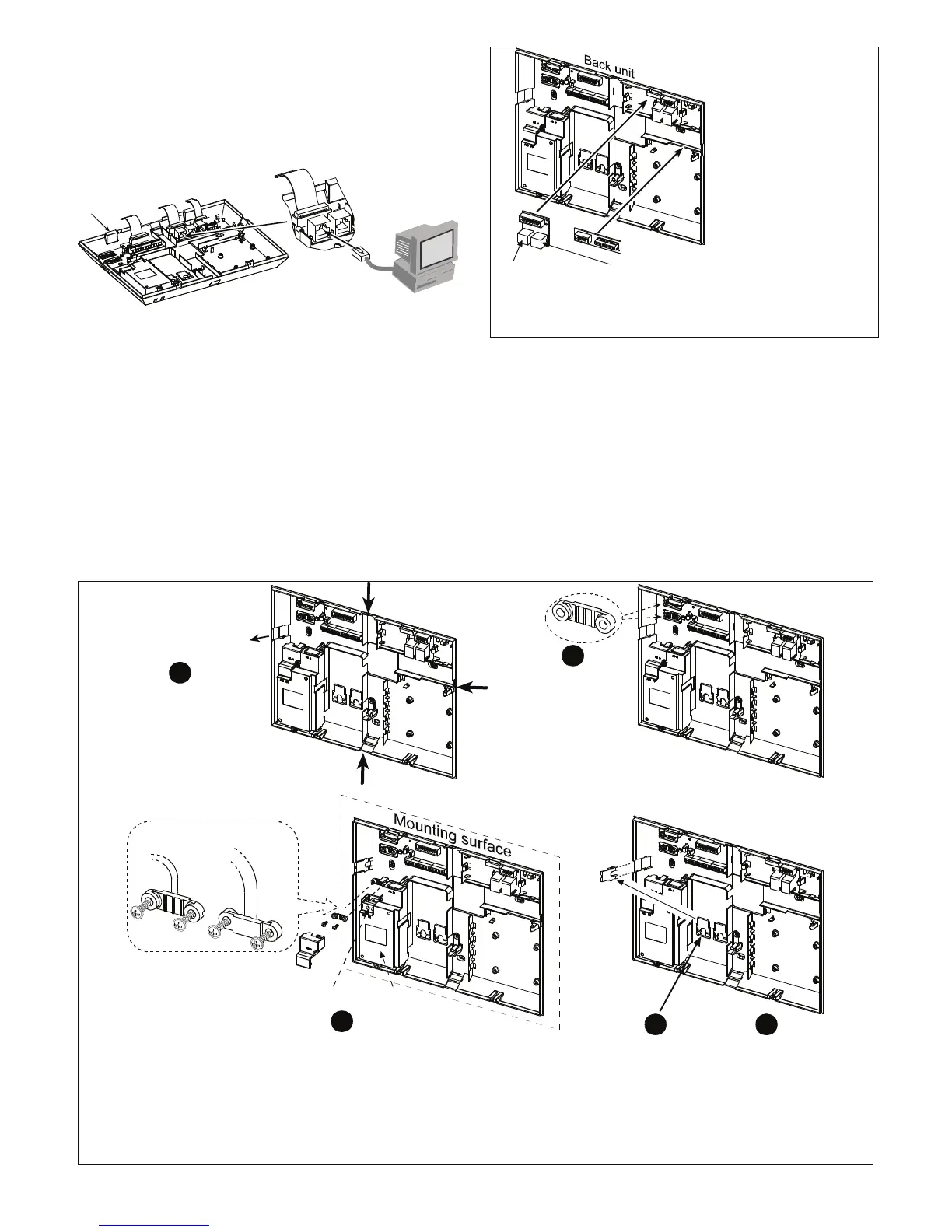
The control panel can be equipped with an optional dual
RS-232 module for serial data interchange with a local
computer (see Figure 3.1d). The dual RS-232 module
permits any two simultaneous device connections such as:
internal PowerLink, Local PC programming, and External
GSM module.
RJ-45 or
RJ-31X (USA)
Dual
RS-232
adapter
Back Unit
Figure 3.1d - Connecting to a Computer
3.5.5 Audio Module Mounting
The Audio module allows the connection of an external wired
Speech box module. The Speech Box is a wired remote
speaker and microphone sensor for indoor use, which
provides remote audio capability to enable two-way voice
communication, between the user and the central station or
private telephone, via the PowerMax Pro control panel.
Press the dual RS-232 and AUDIO modules into the
marked locations (see Figure 3.1e), until a click is heard.
1
2
Connector for
internal
POWERLINK
or PC
Connector for
GSM or PC
1. Dual RS-232 module.
2. Audio Module
Note: The Audio
Module terminal strip
should be wired to the
external Speech Box
terminal strip, according
to the markings on both
terminal strips.
Figure 3.1e - Other Optional Modules Mounting
3.5.6 Power Cable Connection
Connect the power cable and close the control panel as
shown in Figure 3.1f.
Socket-outlet shall be installed near the equipment and
shall be easily accessible.
The connection of the power supply to the PowerMax Pro
unit can be performed through two options, as follows:
Through connection of the power cable to the internal
power supply, as shown in Figure 3.1f.
-or-
Through direct connection of the 12.5 VDC power supply
to the expander card via the wall mounted switched AC/DC
power supply (supplied by Visonic), as shown in Figure
3.1g.
Extract either of
these cable clamps
for use in the next
step.
1
2
Remove the cable
entry knockout(s)
and enter the power
cable.
Power supply
safety cover
Power cable clamp options
Power
supply unit
For thin
cable
For thick cable
(reversed clamp)
a) Insert the power cable through the desired wiring channel (see step 1) and
route it to the power supply unit.
b) Pull out the power supply safety cover.
c) Connect the two wires of the power cable to the power supply terminal strip
with screwdriver.
d) Verify that the wires are tightly fastened by the screws of the terminal strip.
e) Fasten the power cable by its clamp (see also step 2 - this clamp can be
reversed to fit thick/thin cable)
f) Close the safety cover.
3
Remove
and use as
cable entry
cover(s)
4
Slide the cable entry
cover along the slots
until it snaps into
place.
5
Power supply
terminal strip
Figure 3.1f - Back Unit Power Cable Connection