D-302541 33
APPENDIX A. Detector Deployment & Transmitter Assignments
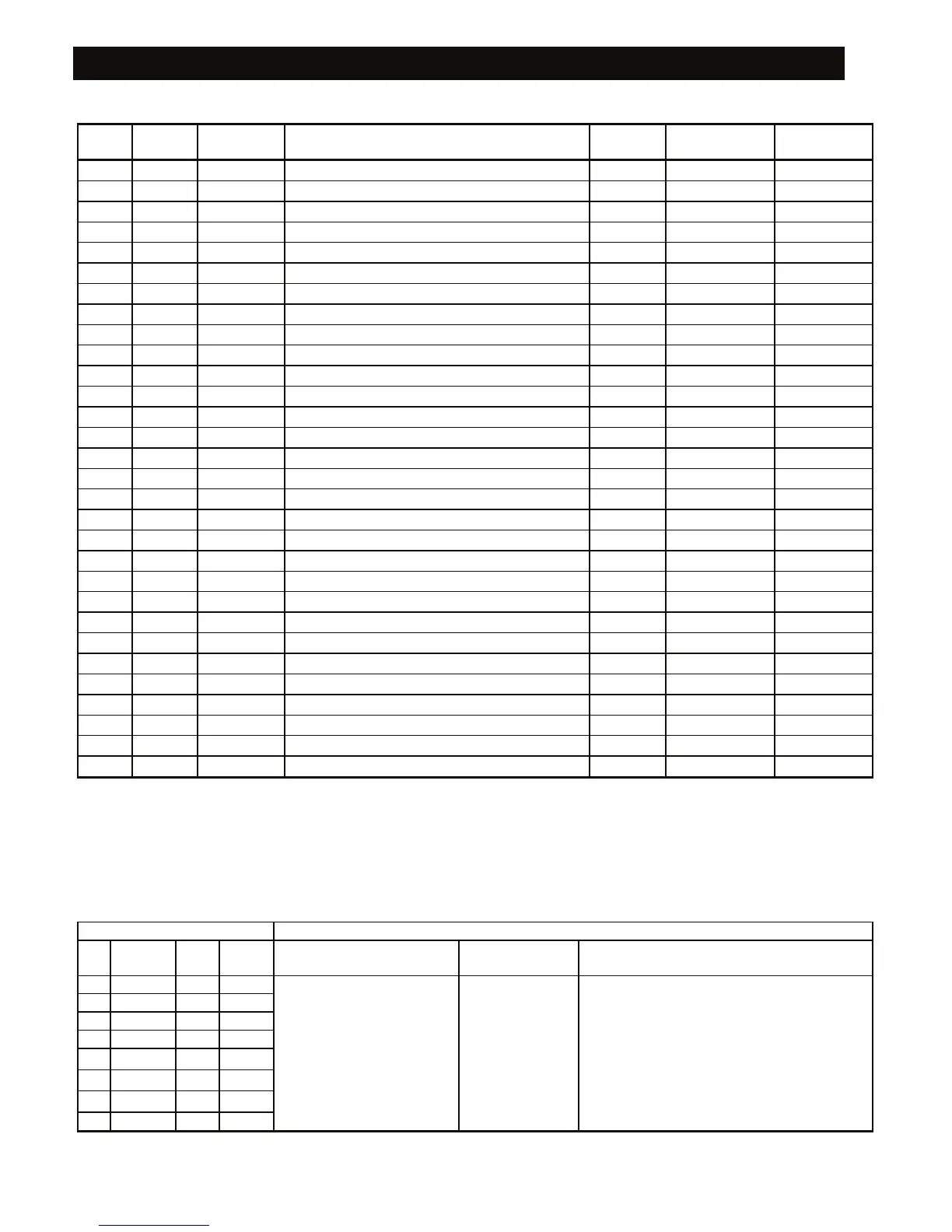
A1. Detector Deployment Plan
Zone
No.
Partition Zone Type Sensor Location or Transmitter Assignment
(in non-alarm or emergency zones)
Chime
(Yes / No)
Controls PGM
(X = YES)
Controls
X-10 Unit No.
1
2
3
4
5
6
7
8
9
10
11
12
13
14
15
16
17
18
19
20
21
22
23
24
25
26
27
28
29 (*)
30 (*)
Zone Types: 1 = Interior follower
<
2 = Perimeter
<
3 = Perimeter follower
<
4 = Delay 1
<
5 = Delay 2
<
6 = 24 h
silent
<
7 = 24 h audible
<
8 = Fire
<
9 = Non-alarm
<
10 = Emergency
<
11 = Gas
<
12 = Flood
<
13 = Interior
<
14 = Temperature
<
15 = Home/Delay
<
16 = Zone Key.
Zone Locations: Note down the intended location for each detector. When programming, you may select one of 26
available zone names (plus 5 custom zone names that you can add - see Figure 4.3 - Define Zones).
* Zones 29 & 30 only are hardwired zones.
A2. Keyfob Transmitter List
Transmitter Data AUX button Assignments
No. Partition Type Holder Status or Arming
“instant”
PGM Control X-10 Unit Control
1
2
3
4
Mark the boxes of the X-10 units to be
activated - see par. 4.8.
5
Indicate the desired function
(if any) – see par. 4.4.17
(Aux button).
Indicate whether
this output will be
activated or not –
see par. 4.8.
1
F 2 F 3 F 4 F 5 F
6
System status
F Yes F No F 6 F 7 F 8 F 9 F 10 F
7
Arming “instant”
F
11 F 12 F 13 F 14 F 15 F
8