D-302541 5
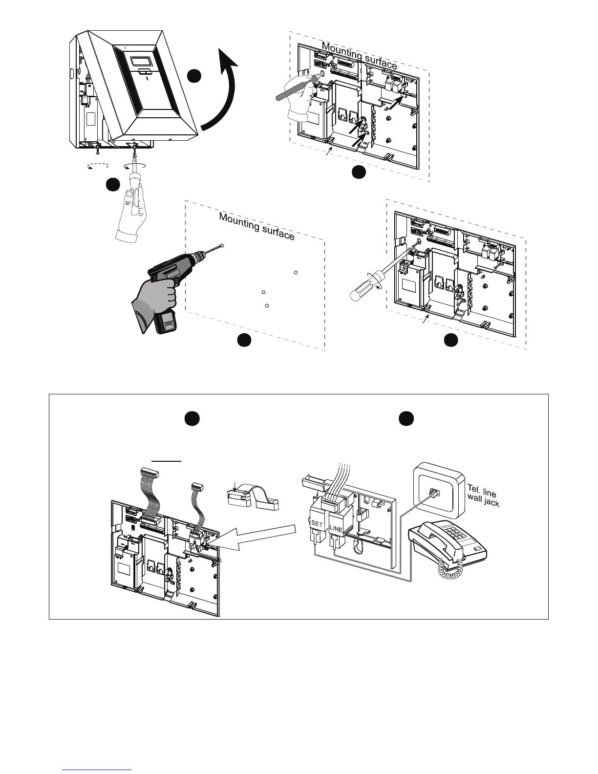
1
2
5
Fasten the back unit with 4 screws
4
Drill 4 holes and insert wall anchors
Release
screws
3
Position the back unit on the desired
mounting location and mark 4 drilling points
on mounting surface
Back unit
Back unit
Separate
the back unit
from the
front unit
Figure 3.1a – Back Unit Mounting
3.5.1 Phone Wiring
1
Connect the receptacles of supplied flat cables
(2 - 5 cables according to options) to the back unit’s plugs.
The receptacles with strain relief clip are for the
front unit -
do not connect to the back unit!
For all countries except north America:
Connect telephone cable to SET connector
and telephone line cable to LINE connector
(through the desired wiring cable entry).
2
Strain relief clip
PHONE WIRING USING RJ CONNECTORS