26 D-302541
BY KEYFOB (upon AUX button pressing in the
keyfob transmitter / MCM-140+, if “PGM/X-10” is
selected in “Define Panel” menu, location 17).
BY ZONES (by disturbance in each
of 3 selected
zones, irrespective of arming / disarming). If you
select toggle, the X-10 output will be turned on upon
event occurrence in these zones and will be turned
off upon next event occurrence, alternately.
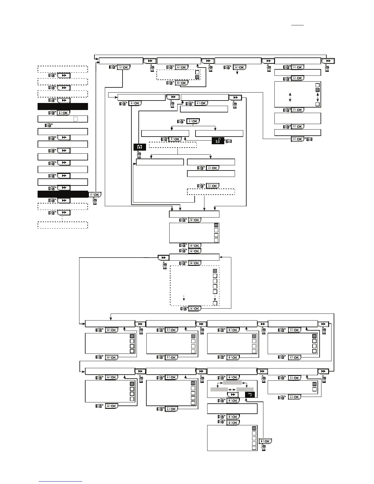
X-10 GENERAL DEFDEFINE INT/STRB X-10 UNIT DEFINE
SET HOUSE CODE
device No. - -
D- -: TYPE/FEATURE
internal siren
strobe
DEFINE PGM
(enter device No.)
house code =A
house code =B
house code =P
(*)
PGM
(*)
PGM
disable
turn on
pulse active
turn off
Dxx: BY DELAY
disable
turn on
pulse active
turn off
disable
turn on
pulse active
turn off
toggle
Dxx: BY KEYFOB
disable
turn on
pulse active
turn off
disable
turn on
pulse active
turn off
disable
turn on
pulse active
turn off
(*)
(**)
PGM
Dxx: BY ZONES
x - zone Z: _ _
(ENTER ZONE NUMBERS)
disable
turn on
pulse active
turn off
toggle
(SELECT BY OR )
a - zone
c - zone b - zone
Note:PGM BY LINE FAIL function is
applicable for PGM only - not for X-10.
by line fail no
by line fail yes
PGM: BY LINE FAIL
(*)
PGM
Dxx: BY DISARM
(*)
PGM
(*)
PGM
(*)
PGM
Dxx: BY ARM AWAY
Dxx: BY ARM HOME Dxx: BY MEMORY
pulse time 2s
pulse time 30s
pulse time 4m
pulse time 2m
Dxx: PULSE TIME
(*)
PGM
USER SETTINGS
ENTER CODE
1. NEW INSTL CODE
2. ENROLLING
4. DEFINE PANEL
[installer code]
INSTALLER MODE
3. DEFINE ZONES
5. DEFINE COMM
INSTALLER MODE
Dxx: LOCATION
See detail “A”
(next page)
attic
back door
basement
bathroom
custom 5
(***)
PLEASE WAIT
if already
enrolled
(Turn X-10 to Learn mode)
Enter learn Mode
ONE WAY UNIT TWO WAY UNIT
<OK> to Enroll
test fail
enroll OKenroll fail
test OK
Enroll FAIL
(Exit X-10 Learn mode)
Exit Learn Mode
PLEASE WAIT
<OK> to test
<OFF> to Delete
8. DEFINE OUTPUTS
9. DEFINE VOICE
<OK> TO EXIT
not installed
WALK TEST
READY
(First display)
Figure 4.8 - Define Outputs Flow Chart