VISUAL
TECHNOLOGY
INCORPORATED,
540
MAIN
STREET,
TEWKSBURY,
MA
01876
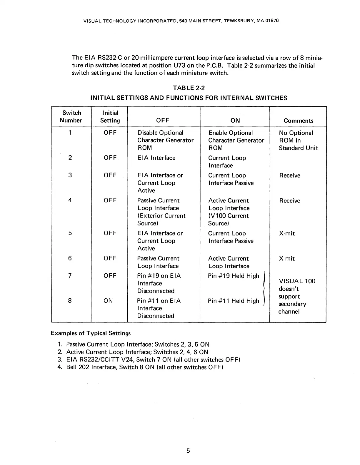
The E
IA
RS232-C
or
20-milliampere current loop interface
is
selected via a row
of
8 minia-
ture dip switches located at position U73 on the P.C.B. Table 2-2 summarizes the initial
switch setting and the function
of
each
miniature switch.
TABLE
2-2
INITIAL
SETTINGS
AND
FUNCTIONS FOR
INTERNAL
SWITCHES
Switch Initial
Number
Setting
OFF
ON
Comments
1
OFF Disable Optional
Enable Optional
No
Optional
Character Generator
Character Generator
ROM
in
ROM
ROM
Standard
Unit
2 OFF
EIA
Interface
Current Loop
Interface
3
OFF
E I A Interface
or
Current Loop
Receive
Current Loop
Interface
Passive
Active
4 OFF
Passive
Current
Active Current
Receive
Loop Interface
Loop Interface
(Exterior Current
(V100 Current
Source)
Source)
5 OFF
EIA
Interface
or
Current Loop
X-mit
Current Loop
Interface
Passive
Active
6
OFF
Passive
Current
Active Current
X-mit
Loop Interface
Loop Interface
7 OFF
Pin
#19
on
EIA
Pin
#19
Held High
Interface
I
VISUAL
100
Disconnected
doesn't
8
ON
Pin #11 on
EIA
Pin #11 Held High
support
secondary
Interface
.channel
Disconnected
Examples
of
Typical Settings
1.
Passive
Current Loop Interface; Switches
2,
3, 5
ON
2.
Active Current Loop Interface; Switches
2,
4, 6
ON
3.
EIA
RS232/CCITT V24, Switch 7
ON
(all other switches OFF)
4.
Bell 202 Interface, Switch 8
ON
(all other switches OFF)
5