VISUAL
TECHNOLOGY
INCORPORATED, 540
MAIN
STREET,
TEWKSBURY,
MA
01876
6.
BUFFERED PRINTER INTERFACE OPTION
6.1
GENERAL
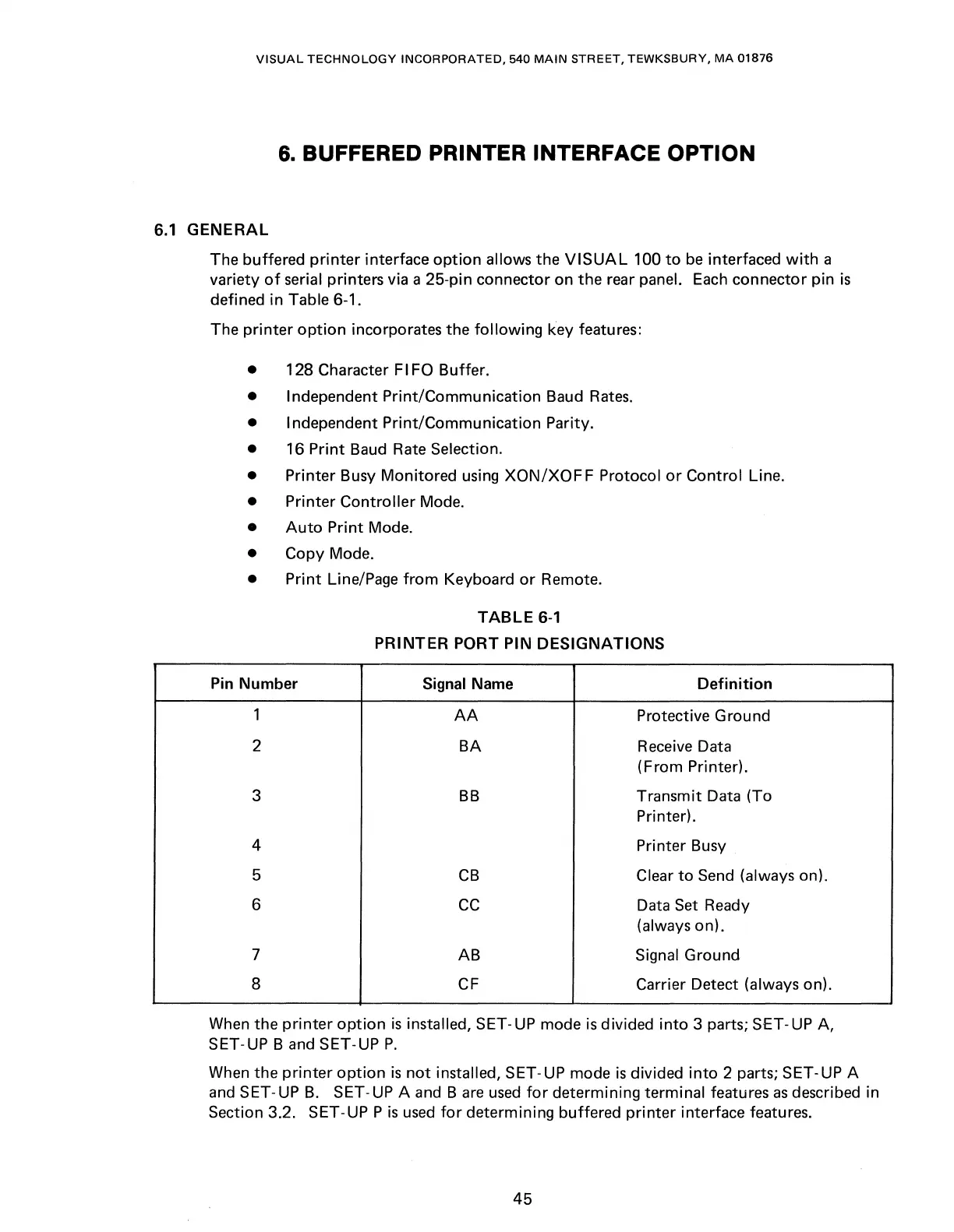
The buffered
printer
interface
option
allows the
VISUAL
100
to
be
interfaced
with
a
variety
of
serial printers via a 25-pin connector on the rear panel.
Each
connector pin
is
defined in Table 6-1.
The
printer
option
incorporates the following key features:
• 128 Character FIFO Buffer.
• Independent Print/Communication Baud
Rates.
• Independent Print/Communication Parity.
• 16 Print Baud Rate Selection.
• Printer Busy Monitored using
XON/XOF
F Protocol
or
Control Line.
• Printer Controller Mode.
•
Auto
Print Mode.
• Copy Mode.
• Print Line/Page
from
Keyboard
or
Remote.
TABLE
6-1
PRINTER PORT PIN DESIGNATIONS
Pin Number
Signal Name
Definition
1
AA
Protective Ground
2
BA
Receive Data
(From Printer).
3
BB
Transmit Data (To
Printer).
4 Printer Busy
5
CB
Clear
to
Send (always on).
6
cc Data Set Ready
(always on).
7
AB Signal Ground
8
CF
Carrier Detect (always on).
When the
printer
option
is
installed, SET-UP mode
is
divided
into
3 parts; SET-UP A,
SET-UP
Band
SET-UPP.
When
the
printer
option
is
not
installed, SET-UP mode
is
divided
into
2 parts; SET-UP A
and SET-UP
B.
SET-UP A and
Bare
used
for
determining terminal features
as
described in
Section 3.2. SET-UPP
is
used
for
determining buffered
printer
interface features.
45