VISUAL
TECHNOLOGY
INCORPORATED, 540
MAIN
STREET,
TEWKSBURY,
MA
01876
3.
START-UP PR9CEDURES
3.1
INSTALLATION
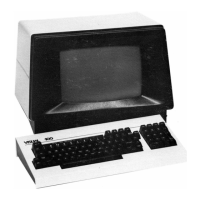
When
installing the
VISUAL
100
for
the
first
time, or when moving the terminal
to
a new
location
or
new communications
trunk,
the following
steps
should
be
followed.
1.
Unpack the terminal
and
place
it
in the desired
work
area.
2.
Tilt
the terminal portion up and
read
the voltage value
from
the serial number tag.
If
the voltage
is
correct, proceed
to
step
4.
3.
If
the voltage
is
incorrect, change the transformer wiring
as
described in
Section 7 .8.
4.
If
the interface
is
EIA,
proceed
with
step
7.
5.
If
the interface
is
current loop, remove the rear panel (Section 7.2)
and
set the
internal switches
as
defined in Table 2-2.
6. Install the rear panel.
7.
Plug
in the Keyboard cable, Interface cable,
and
Printer cable
into
the correspond-
ing connector.
8.
Power on the terminal.
9.
If
intensity
is
too
low, cursor
not
visible,
press
SET-UP key once, then
press
and
hold the t key
until
the
screen
presentation
is
visible.
10. Proceed
with
SET-UP procedure
as
described in Section 3.2.
3.2 SET-UP MODES
3.2.1 General
The
VISUAL
100
does
not
use
exterior switches
or
jumpers
to
determine which built-in
terminal features
will
be
on
or
off.
Instead, a nonvolative RAM memory
is
used
to
remem-
ber which features
are
enabled
and
disabled. Terminal features
are
selected and stored in a
special mode called SET-UP mode.
When
SET-UP mode
is
entered, the status
of
terminal
features
is
displayed on the
screen.
You
can
then
change
the terminal features
to
any
desired configuration. Once the desired configuration
is
selected, the terminal
will
function
per the new configuration on either temporary
basis
(by exiting SET-UP mode)
or
fixed
basis
(by performing the SAVE operation).
SET-UP mode
is
divided
into
two
parts; SET-UP A and SET-UP
B.
*SET-UP
A shows
whether
an
80
or
132 column
screen
format
is
selected and
also
displays the location
of
each
columnar tab stop.
Each
SET-UP A feature
is
described.in detail in Section 3.2.2.
SET-UP B summarizes the status
of
other terminal features and
is
described in detail in
Section 3.2.3. Table
3-1
summarizes the various features
that
are
determined in SET-UP
A and SET-UP
B.
*If
the
buffered printer option
is
selected, SET-UP mode
is
divided into 3 parts, see Section
6.
9