PARTS
12 CHAPTER 2
2.10 SENSOR PCB DETECT
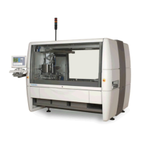
FIGURE 2.16 SENSOR
Part nr. 38278
Description Sensor photo Baumer FHDM 12P5001/S35A
Sensor B27 Disable width adjustment (if FluxerMask present)
Sensor B28 PCB present on station 4A (outfeed on infeed side)
Sensor B29 PCB at exit station 4A (outfeed on infeed side)
Sensor B71 PCB at exit station 4
Sensor B72 PCB present on station 4
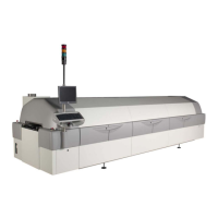
2.10.1 WORKING PRINCIPLE
FIGURE 2.17 WORKING PRINCIPLE SENSOR
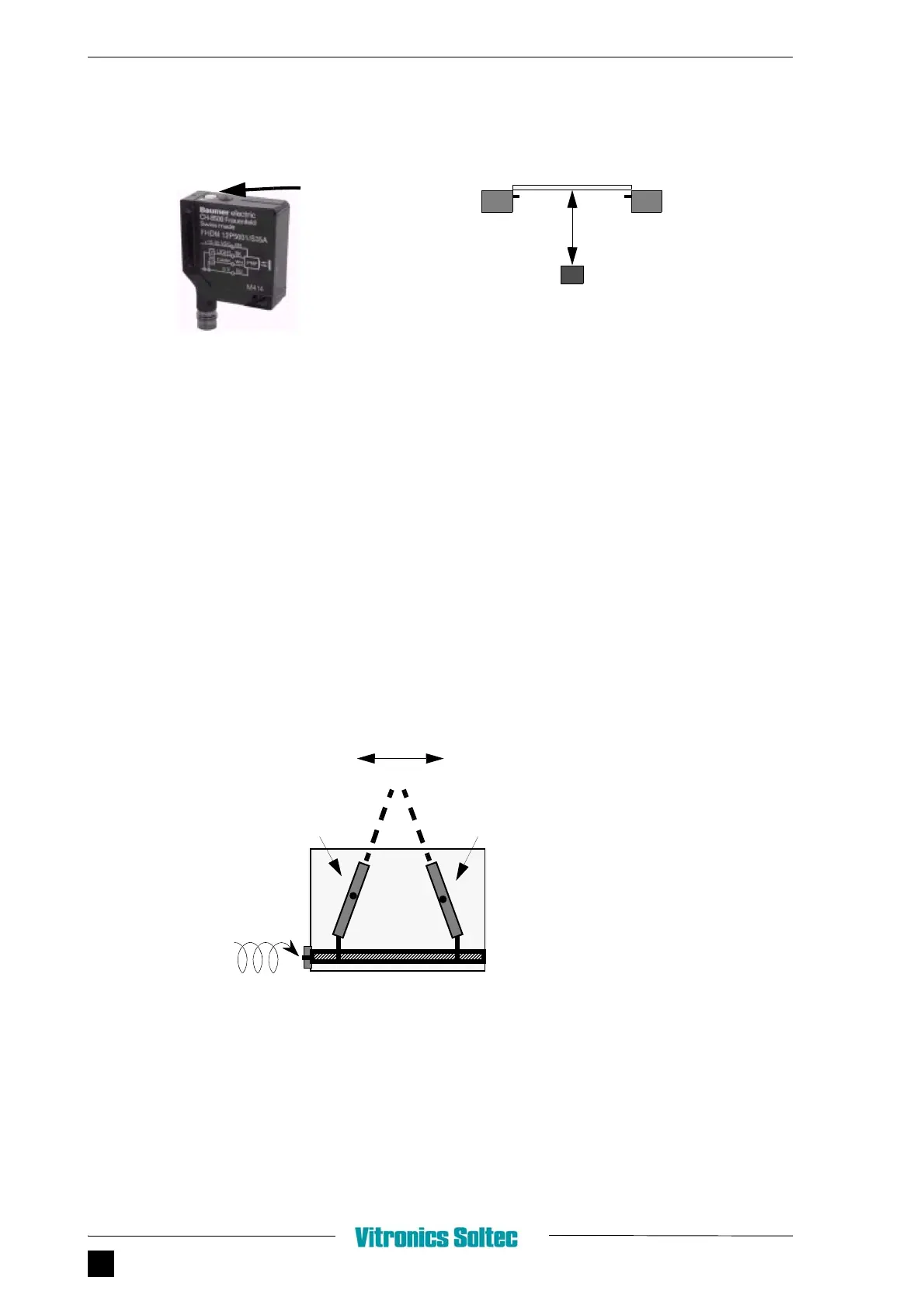
2.10.2 ADJUSTMENT PROCEDURE
1. Place PCB on the conveyor bars, just above the sensor.
2. Adjust sensor on a switching distance ±72 mm. (Sensor must be activated).
ADJUSTMENT SCREW
PCB
SENSOR
72 mm
BAR BAR
TRANSMITTER
RECEIVER
SENSOR HOUSING
ADJUSTMENT SCREW
BEAMS
WIDTH ADJUSTABLE
(MULTIPLE TURN)
it
t
e a
justment screw t
e ang
e
between the transmitter & receiver can be
changed. This means that the energy in the
sensor is always the same. The adjust-
ment screw only changes mechanical the
angle.
The operating range of the sensor is
adjustable between 15 to 150 mm.