10 | EN EN | 11
gallons of continuous ow, the
aquastop valve automatically
shuts off the water supply.
1
2
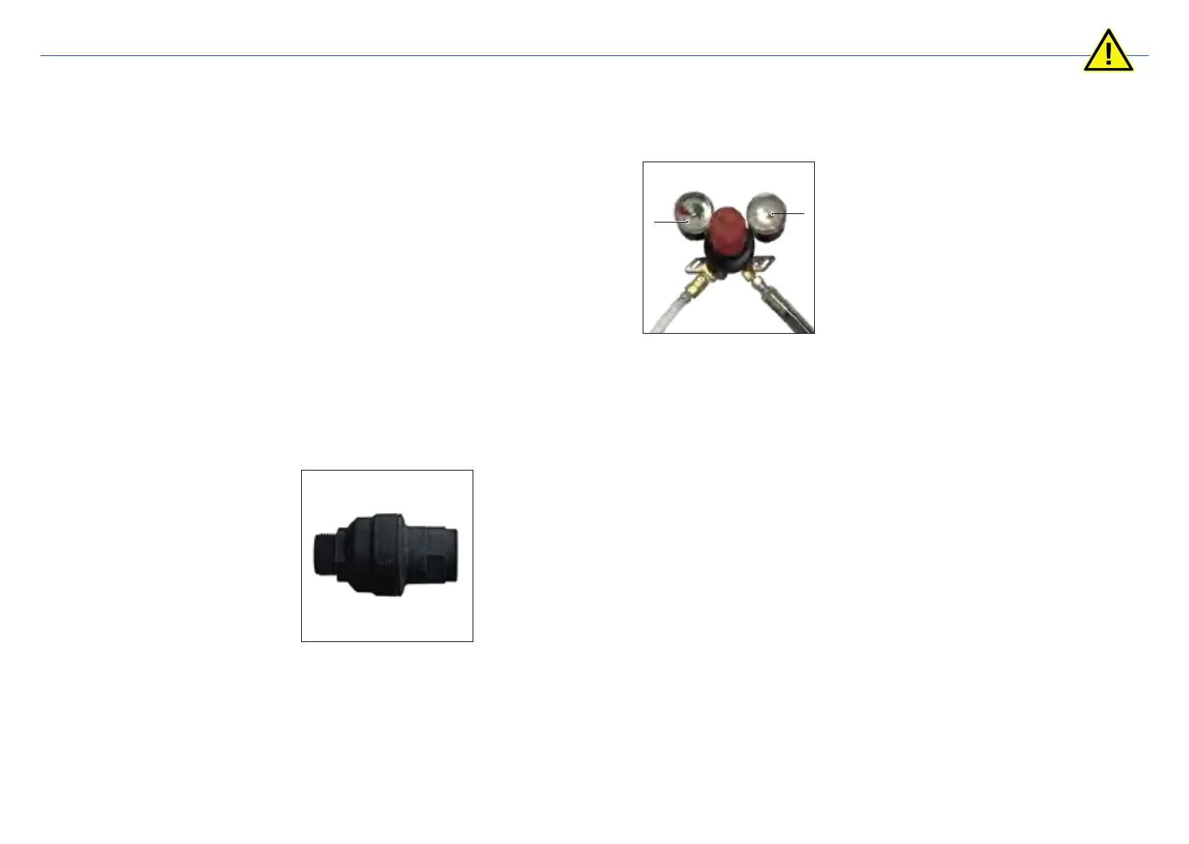
CO
2
pressure regulator and
pressure relief valvee
The CO
2
pressure regulator is
mounted on the CO
2
bottle. The
mounted gauge indicates the
applied CO
2
pressure in PSI.
The left gauge 1 indicates the
CO
2
pressure and the lling level
of the CO
2
bottle.
The right gauge 2 indicates the
CO
2
pressure applied to the
appliance. The optimum setting
is 4.5 bar / 65 psi.
For additional safety, the CO
2
pressure regulator has a pres-
sure relief valve.
Water pressure regulator
According to ASEE1022 the
water dispenser is installed with
a water pressure regulator and a
controllable backow preventer.
The water pressure regulator
reduces the inlet water pressure.
The water pressure regulator
is preset to 4 bar / 58 psi. This
pressure must not be changed
without authorisation.
Axed labels and notices
Danger due to illegible
labeling!
Over time, stickers and signs
may become dirty or indecipher-
able for other reasons, meaning
that dangers are not recognized
and necessary operating in-
structions cannot be followed.
There is danger of injury as a
result.
• Always keep all safety, warn-
ing and operating instructions
clearly legible.
• Replace damaged signs or
stickers immediately.
Spare parts
The use of incorrect spare parts
and lters can cause damages
and malfunctions of the water
dispenser.
• Only use original spare parts
and lters from VIVREAU or
spare parts and lters ap-
proved by VIVREAU. The de-
vice must be connected to the
water supply using new pipes
only. Old hoses must never be
reused.
• Never attempt the unau-
thorized repair of the water
dispenser.
• Servicing shall be done by
factory authorized serivce
personnel, so as to minimize
the risk of possible ignition due
to incorrect parts or improper
The operator is responsible for
the following:
• The installation and initial com-
missioning of the appliance
may only be carried out by
qualied persons.
• The requirements in terms of
the installation location dened
in these instructions (see “Lo-
cation” on page 15) must be
fullled at all times.
• Prior to operation of the wa-
ter dispenser, the instructions
must be read in their entirety
and understood.
• The cleaning, maintenance
and repair intervals described
in these instructions must be
observed.
• Maintenance work may only
be carried out by qualied
personnel.
• The initial commissioning as
well as all cleaning, disinfec-
tion and repair work must be
recorded in the log book.
• The operating instructions for
the replacement of CO
2
bot-
tles must be afxed near the
CO
2
bottle and must be clearly
legible.
• In addition to the safety notes
in these instructions, the ap-
plicable regulations for safety,
hygiene, health and safety as
well as environmental protec-
tion at the place of use must
be observed.
• The operator should contact
the local authorities to check
the local and regional require-
ments for the installation of
devices connected to the pub-
lic water supply.
Safety equipment
Danger through malfunction-
ing safety equipment!
If safety equipment is not func-
tioning or is inoperative, there is
a danger of very severe injury or
death.
• Before starting up, check that
all safety equipment is in good
working order and correctly
installed.
• Never make safety equipment
inoperative or bypass it.
• Ensure that all safety equip-
ment is accessible at all times.
The safety equipment installed
in the device is listed below.
Aquastop
The aquastop is located be-
tween the water shut-off valve
and the water supply of the
water dispenser. A sensor inside
detects the quantity of water
passing through. When the
registered amount exceeds 2.6
Safety instructions