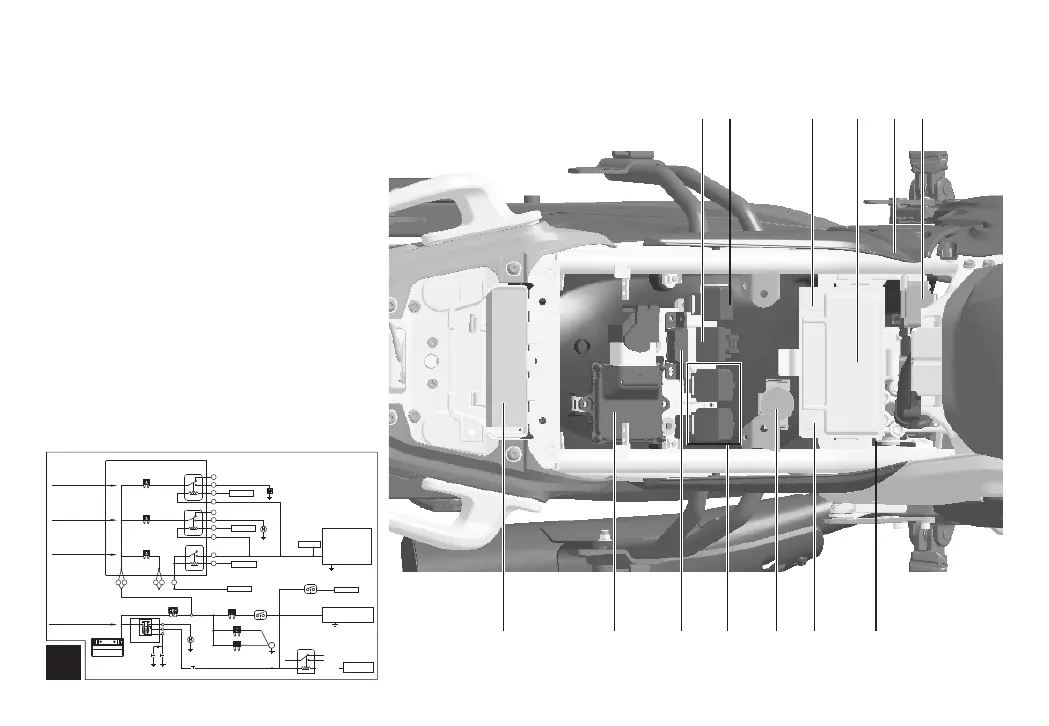
Underneath the seat
24.Fuse box
25.Flasher
26.Battery anode
27.Accumulator
28.Electrical box
29.Toppling switch
30.ABS controller
31.Battery cathode
32.Starting relay
33.Supplementary relay
34.Diagnose interface
24
27
29
30
32
34
35
36
33
28
4
25
26
31
35.ECU
36.Tools
4 way fuse and control relay diagram(There are 6 branches
for motorcycle power supply, which get power for positive
pole of battery and with 1 fuse each, who are independent
without interference.)
3~5A about50W
2A about30A
4.5~6A about67W
F3 10A
F2 10A
F1 15A
Fan relay
K3
1
2
3
4
5
14
13
12
15
8
7
6
5
11
10
Grey/Red
Grey/White
Purple
Brown/Green
Brown/Black
Purple
Brown/Red
ECU P45
ECU P46
ECU P14
ECU P33
Fan
10A 15A
25A 30A
Fuel pump relay
K2
1
3
2
5
4
Main relay
1
2
5
4
3
K1
3 4
1 2 9
Red/White 1
Red Red
Red
Red/White 1
F1 30A
F2 10A
Red 2
Circuit of ABS,
Lighting and Signal
3~30A
Red/White
Battery jar
starting relay
starting dynamo
Electric start button
ignition lock
Black
White/Red
White/Blue
F3 25A
F4 10A
Black
ABS
Black
right handle flameout switch
ECU P32
Black
Green/Pink
1
3
4
5
2
Circuit of main relay
Circuit of oil pump
Circuit of Cooling fan
Specification of safety insert:
Original interior drawing of electrical parts box
Purple Purple Purple
Oil pump
ECU, oxygen se nsor,
Diagno se interf ace,
carbon c anister,
fuel spr ay nozzle ,
FBT
Black/White
Black
Lighting and signal system
Lamps, instruments,
speakers
Green/Red
White/Black
Red/White1
Red/White1
Red/White 1
Clutch
Switch
Neutral SW
Light green/Red
Green/Red
Yellow/Red
Lat eral s uppor t
fla meout
ECU P8