3.Junior User Guidebook
Control Area
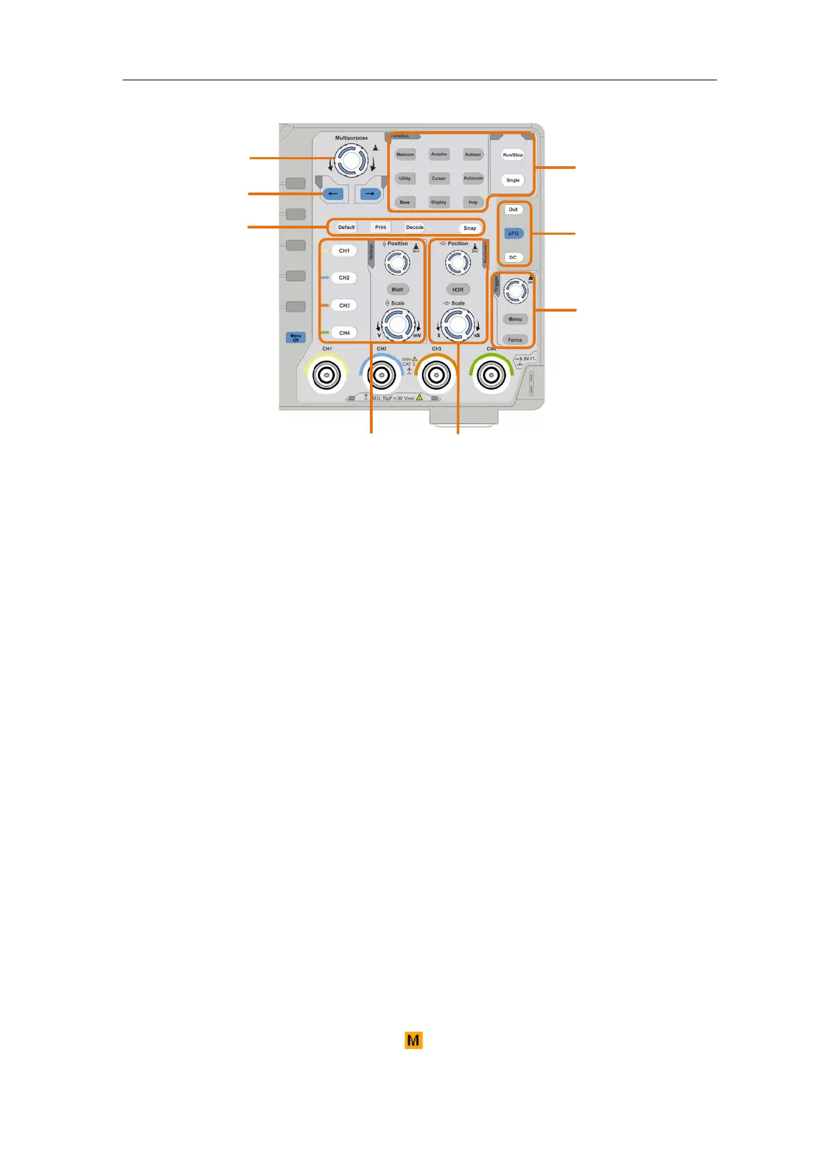
Figure 3-3 Control Area Overview
1. Function button area: Total 11 buttons
2. Waveform generator controls (optional)
or
DAQ: This function is not available.
P/F: Pass/Fail (see "Pass/Fail" on P74)
W.REC: Waveform Record (see "How to Record/Playback Waveforms" on P64)
3. Trigger control area with 2 buttons and 1 knob.
The Trigger Level knob is to adjust trigger voltage. Other 2 buttons refer to trigger
system setting.
4. Horizontal control area with 1 button and 2 knobs.
"HOR" button refer to horizontal system setting menu, "Horizontal Position" knob
control trigger position, "Horizontal Scale" control time base.
5. Vertical control area with 5 buttons and 2 knobs.
CH1 - CH4 buttons correspond to setting menu in CH1 - CH4. "Math" button
provides access to math waveform functions (+, -, ×, /, FFT, user function, digital
filter). The "Vertical Position" knob control the vertical position of current channel,
and the "Scale" knob control voltage scale of current channel.
6. Default: Call out the factory settings.
Print: Print an image of what appears on the instrument screen.
Decode: Turn on/off Decode function.
Snap: Shortcut button for measurement snapshot.
7. Direction key: Move the cursor of the focused parameter.
8. M knob (Multipurpose knob): when a symbol appears on the menu, it indicates
you can turn the M knob to select the menu or set the value. You can push it to close
 Loading...