3.Junior User Guidebook
the menu on the left and right.
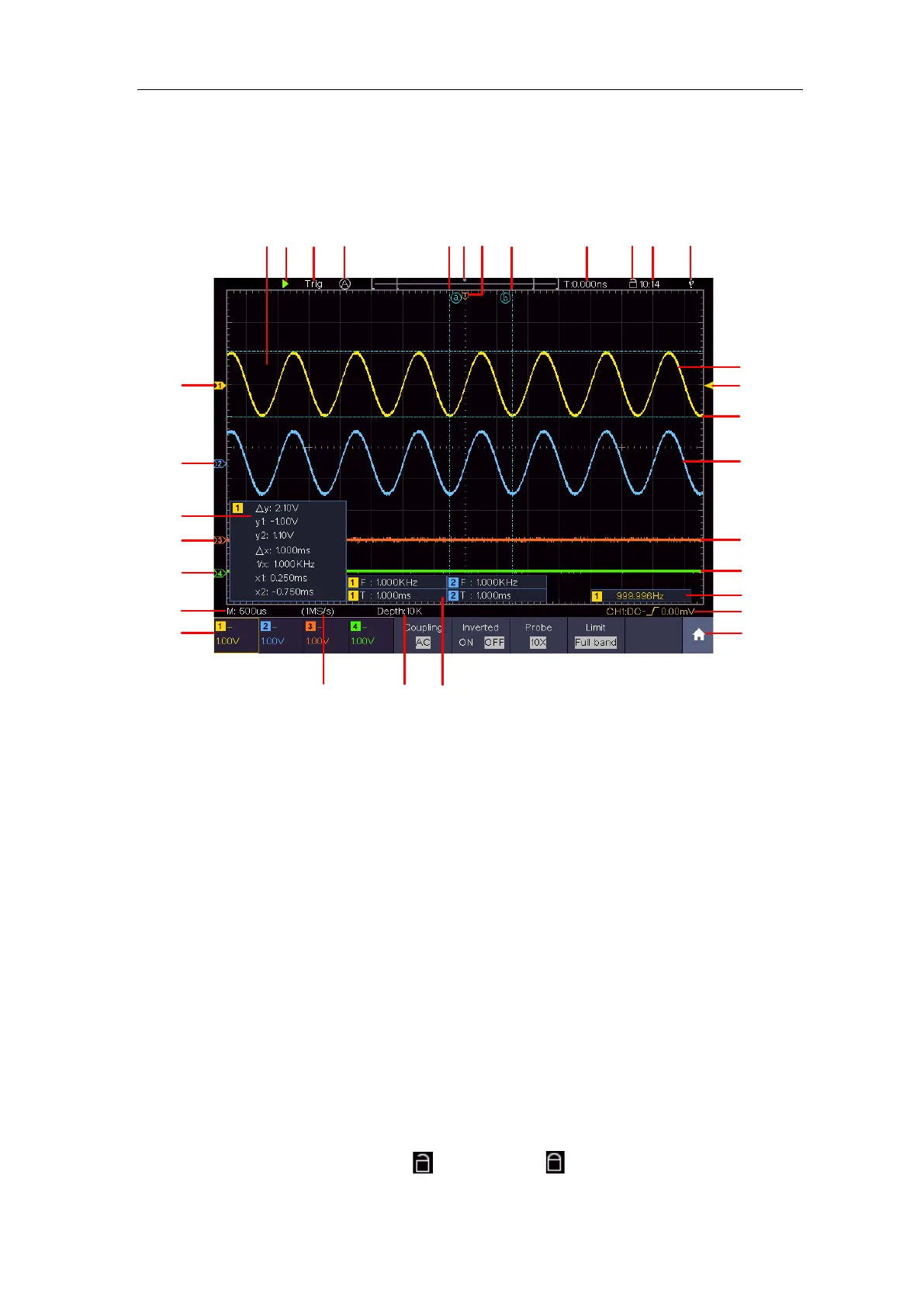
User Interface Introduction
1
3
9
19
13
27
24
6
8
10
11
14
15
20
22
28
30
7
25
2
4
5
23
12
5
18
29
16
17
21
26
Figure 3-4 Illustrative Drawing of Display Interfaces
1. Waveform Display Area.
2. Run/Stop (touchable) (see "How to Use Executive Buttons" on P87)
3. The state of trigger, including:
Auto: Automatic mode and acquire waveform without triggering.
Trig: Trigger detected and acquire waveform.
Ready: Pre-triggered data captured and ready for a trigger.
Scan: Capture and display the waveform continuously.
Stop: Data acquisition stopped.
4. Click to auto set.
5. The two blue dotted lines indicates the vertical position of cursor measurement.
6. The pointer indicates the trigger position in the record length.
7. The T pointer indicates the horizontal position for the trigger.
8. It shows present triggering value and displays the site of present window in
internal memory.
9. Touchable icon is to enable (
) or disable (
) the touchscreen controls.
10. It shows setting time (see "Config" on P73).
 Loading...