4.Advanced User Guidebook
Stop
Trigger when SDA data transitions from low to high
while SCL is high.
Ack Lost
Trigger when SDA data is high during any
acknowledgement of SCL clock position.
Address
Trigger on the read or write bit when the preset
address is met.
Adr
For
mat
Set Address Bits to be “7”、“8”or“10”.
Set address according to the preset address bits,
address range is 0-127, 0-255, 0-1023 respectively.
Set Data Direction to be Read or Write.
Note: The set is not available when Address bits is set
to “8”.
ess
Data
Search for the preset data value on SDA and trigger on
the dump edge of SCL of the last bit of the data area.
DatF
orma
t
lengt
Set data byte length, available range 1-5 bytes. Adjust
M knob or click to set byte length.
Select the data bit, ranges from 0 to (byte length*8 -1).
Set data to be H, L or X (H or L)
Set all the data bits to be the specified value in Data
entB
Addr / Data
Trigger when Address and Data conditions are met at
the same time .
Normal
Acquire waveform even no trigger occurred
Acquire waveform when trigger occurred
When trigger occurs, acquire one waveform then stop
3. SPI Trigger
Trigger on the specified data when the timeout condition is meet. When using SPI
trigger, you need to specify the SCL and SDA data sources.
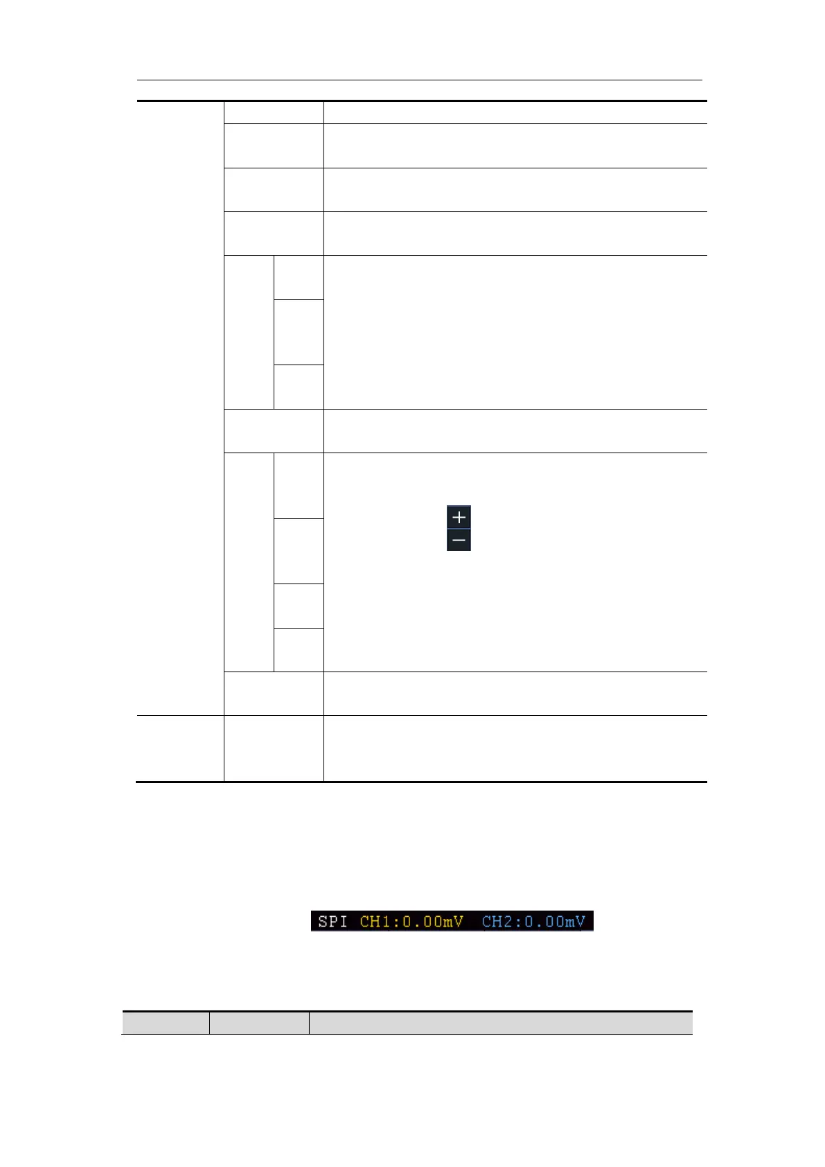
In SPI bus trigger mode, the trigger setting information is displayed on bottom right
of the screen, for example, ,indicates that
trigger type is SPI, CH1 trigger level is 0.00mV, CH2 trigger level is 0.00mV.
SPI Trigger menu list:
 Loading...