VTI Instruments Corp.
10 EX1200 Switch Card Introduction
321H
S
ECTION
1
I
NTRODUCTION
O
VERVIEW
Signal switching is at the heart of every automated test system. It is responsible
for routing signals
of interest between test system instruments and the device
under test (DUT). The purpose of the
testing is to improve product quality. The
switch distributes instrument I/O, which can reduce
overall system cost. Since
switching is effectively an extension of the instrument, it should be
transparent
to the overall system. EX1200 switching products employ extensive signal shielding
and high-quality relays to ensure that the test system is “minimally aware” of the
switch’s
presence.
P
LUG
-
IN
M
ODULE
I
NSTALLATION
All EX1200 series switch cards must be installed into an EX1200 series mainframe to be used.
The mainframe operates on 90 V to 250 V at 50 Hz/60 Hz which is used to supply the cards the dc
voltages required for the cards to function properly. Before installing a plug-in module into an
EX1200 series mainframe, make sure that the mainframe is powered down. Insert the module into
the base unit by orienting the module so that the circuit board of the module can be inserted into
the slot of the base unit. Position the cover so that it fits into the module’s slot groove. Once the
module is properly aligned, push the module back and firmly insert it into the backplane
connector.
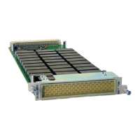
F
IGURE
1-1:
M
ODULE
I
NSTALLATION
(EX1200-3048
S
HOWN
)
NOTE To maximize air flow for cooling, blanking panels (P/N: 41-0472-012) should be installed into the
empty slots of EX1200 mainframes.
 Loading...