VTI Instruments Corp.
48 EX1200-3048S Plug-in Module
EX1200-3048S
P
LUG
-
IN
M
ODULE
48-C
HANNEL
T
WO
-W
IRE
FET
M
ULTIPLEXER
The EX1200-3048S is a high-density FET multiplexer module designed for scanning of multiple
points to a common bus, in either 2- or 4-wire configurations, either synchronously with the
EX1200 system DMM scan function, or asynchronously as a system switch to other devices
through LXI LAN messages or the hardware trigger bus. The solid-state design delivers maximum
switching speed and near infinite life. Up to 288 two-wire (or 144 four-wire) channels can be
accommodated in a 1U EX1200 full rack mainframe for maximum density, or mixed and matched
with other EX1200 plug-ins for flexibility. Typical applications include temperature and voltage
data acquisition and data logging at up to 1000 scans per second.
The EX1200-3048S consists of dual (1x24) 2-wire multiplexer banks. Each bank can be
interconnected within a module under program control (via bussing relays) and across modules via
the EX1200 analog bus to configure larger multiplexers as required. This eliminates external
wiring and helps reduce unterminated stubs. Internal residual voltage discharge relays can be
enabled to momentarily short out the measurement path when changing from one input channel to
the next. This dissipates any voltage held by the wiring and instrument input capacitance. These
relays protect sensitive devices, such as CMOS circuits, from residual voltages caused by previous
high-voltage measurements. This feature can also be disabled in low-voltage applications where
maximum throughput speed is important.
The EX1200-3048S can be controlled programmatically using IviSwtch-compliant calls. Both
path level programming and individual relay control are available. Refer to the host driver
documentation for additional details.
345H
Figure 4-17 provides a logical diagram of the switch module
and identifies the switches used by the module. This information can be used for individual relay
control through the driver. An optional terminal block provides screw termination points for
external field wiring. This terminal block also includes cold junction compensation reference for
more precise temperature measurements.
C
ONNECTOR
P
INS AND
S
IGNALS
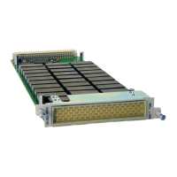
F
IGURE
4-16:
EX1200-3048S
F
RONT
P
ANEL
(F
RONT
V
IEW
)
 Loading...