www.vtiinstruments.com
EX1200-3824 Plug-in Module 69
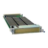
EX1200-3824
P
LUG
-
IN
M
ODULE
8
(1
X
24)
S
OLID
S
TATE
,
100V/100
M
A
M
ULTIPLEXER
The EX1200-3824 is a high speed multiplexer designed to provide flexible switching multiplexing
architecture with 8 banks of 1 x 24 one-wire multiplexers. Upto 48 1 x 24 one-wire channels can
be accommodated in a 1U EX1200 full rack mainframe for maximum density, or mixed and
matched with other EX1200 plug-ins for flexibility. The solid-state design delivers maximum
switching speed and near infinite life.
The EX1200-3824 may be used in applications in which its inputs are connected to DUT capable
of producing signals that approach 100 V, with its commons being connected to high-speed
measurement devices. In this type of applications, the input signal will need to be attenuated. For
this very reason EX1200-3824 also has attenuator option, this will consist of user configurable
10KHz Low Pass Filter or 400KHz Low Pass Filter, refer to Figure 4-28 for configuring the LPF.
The EX1200-3824 can be controlled programmatically using IviSwtch-compliant calls. Both path
level programming and individual relay control are available. Refer to the host driver
documentation for additional details. Figure 4-29 provides a logical diagram of the switch module
and identifies the switches used by the module. This information can be used for individual relay
control through the driver.
EX1200-38TB the break out box (BOB) can be used along with the EX1200-3824. This EX1200-
38TB can be mounted on the EX1200-3824 front panel, mates with 200 Pin connector directly.
EX1200-3824
S
TANDARD
B
OARD
Figure 4-24 explains the EX1200-3824 without Attenuator option. For the standard configuration
a 0 Ohm resistor bypasses the attenuator circuit bringing out the 8 commons to the 200 pin front
panel. This functions as a multiplexer module of 8 banks (1 x 24).
FIGURE
4-24:
I/O
IMPLEMENTATION
,
STANDARD
EX1200-3824
B
OARD
EX1200-3824
WITH
A
TTENUATOR
O
PTION
Figure 4-25 exlains the EX1200-3824 with Attenuator option, the 0 Ohm resistor is removed and
the Mux outputs are fed through the attenuator circuit. The 8 common pins in the standard board
will be treated as Ground Pins for connecting the DUT. Ground pins are dedicated to each bank
contributing a total of 8 ground pins at the Front Panel Connector.
Attenuator Section comprises of two different user selectable low pass frequency options – 10 Khz
and 400Khz. Jumpers are provided to select the frequencies. 10Khz LPF is selected if jumper is
connected. 400 Khz LPF is selected if jumper is not connected. Refer Figure 4-28
 Loading...