VTI Instruments Corp.
150 EX1200-7100 Plug-in Module
EX1200-7100
C
ARRIER
F
RONT
P
ANEL
C
ONNECTORS
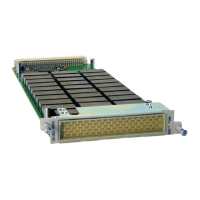
The EX1200-7100 carrier provides six lines of control for external microwave switches. Using a pass
through adapter (VTI P/N: 70-0146-026), external microwave switches can be connected to the three 14-
pin connectors located inside the carrier. The signals for the connector pins are shown in Table 4-2.
Connector Pin Signal
A
+24V
B
RELAY 1
C
RELAY 2
D
RELAY 3
E
RELAY 4
F
RELAY 5
H
RELAY 6
J
Not Used
K
Not Used
L
Not Used
M
ID0
N
ID1
P
ID2
R
ID3
T
ABLE
4-54:
EX1200-7100
C
ONNECTOR
P
INS AND
S
IGNALS
EX1200-7100
S
OFT
F
RONT
P
ANEL
Although soft front panel (SFP) operation is detailed in the EX1200 Series User’s Manual, the EX1200-
7100 has a unique input/output interface that is available when a pass through adapter is used. When the
SFP is initially viewed, a PIOx_y (PIO1_2 in Figure 4-5) the slot is viewed. From here, the user can enter
the value that will be input or output by the relay driver. When PIO1_2 is clicked, the slot expands to show
the seven bits that are controlled when the input/output is set.
F
IGURE
4-69:
S
TANDARD
(L
EFT
)
AND
E
XPANDED
(R
IGHT
)
I
MAGE FOR
PIO1_2
P
ORT
 Loading...