www.vtiinstruments.com
EX1200 Switch Card Introduction 11
The maximum safe voltage for an EX1200 system is determined by the plug-in card with the
lowest voltage rating.
M
ICROWAVE
M
ODULE
I
NSTALLATION
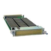
For the EX1200-7100 Plug-in Module, microwave switch modules can be installed. Before
installing a switch module into the EX1200-7100 carrier, ensure that the mainframe is powered
down. Insert the switch module into the desired slot of the carrier. Slide the module into the
mating connector at the rear of the carrier using the two guide pins to ensure proper orientation.
Once the guide pins are aligned, push the module firmly mating connector. The module is then
sMUXred to the front panel of the carrier using four socket head cap screws.
F
IGURE
1-2:
M
ICROWAVE
S
WITCH
I
NSTALLATION
MODULE SHIELDING/GROUNDING
Most EX1200 modules incorporate an integral shield into the design of the PCB that attenuates
noise and crosstalk between adjacent channels/modules. To properly utilize this feature, tie the
appropriate front panel connector pins to the mating cable’s common shield and/or ground. If this
feature is present on a module, the pins are identified in the module appendix in the Connector
Pins and Signals table and the signal is noted as “SHIELD”.
Leaving the SHIELD pins unconnected may have detrimental effects on signal crosstalk and
isolation. If no cable shield connection is available, chassis ground may be used to attach the
SHIELD pins.
Many plug-in modules also incorporate ground pins, labeled “GND_C” or simply “GND”. These
pins tie the module to chassis ground. Note that the SHIELD pins are not tied to ground and have
no electrical connections.
S
CANNING
The EX1200 switch cards provide scanlist functionality to maximize measurement throughput.
The scanlist allows the relay state to be advanced by a hardware trigger rather than requiring the
state of the relay to be updated manually during program execution. Doing this eliminates the need
to wait on the controller to wait for a state to be settled and send the command to update relays
providing maximum throughput performance
 Loading...