Page 50 of 102 Page 51 of 102Doc: DRX Installation
Version: 7.1 January 2021
Doc: DRX Installation
Version: 7.1 January 2021
wassp.com wassp.com
DRX INSTALLATION MANUAL DRX INSTALLATION MANUAL
5.2.8.2. Configuring Height Relative to the Internal GPS Geoid
The internal GPS Geoid can be used if a DRX Geoid file is not available for your area.
Deselect GEOID FILE CORRECTION and hit COMMIT.
An oset can be applied to the Internal GPS Geoid. This can be applied under the DATA
SETUP tab in the DRX SETUP WEBPAGES.
See “Appendix D - Ship’s Measurement Points” on page 94, Sea section Level Height
using Internal GPS Geoid for details on the calculated sea height using Internal GPS
Geoid.
5.3. COMMISSIONING STEP 3: ON WATER PATCH TESTS
On water patch tests are essential for correctly configuring the DRX. The accuracy of the
values derived from these patch tests will directly impact system performance.
These patch tests can be run using various tools including those in 3rd Party application
such as HYPACK, WASSP Patch Test Utility shipped with WASSP CDX or manually through
WASSP CDX. The sections below describe methods for running patch tests manually
using WASSP CDX.
5.3.1. GPS Time Delay
Most GPS sources used in conjunction with WASSP will have a significant delay between
when the ship passes through a position and when that position is sent on the serial port.
This delay may be in the order of 1 second. This means at 10 knots an object will move
10 metres if passed in opposite directions at this speed.
IMPORTANT NOTE: NMEA Buer and multiplexers can add significant
delays to serial data. Any configuration change will require recalculation of
delays. All connections from sensors should be direct to DRX.
NOTE: If using PPS input to synchronise to UTC time (configured through
the DRX SETUP WEBPAGES) the GPS time delay will be automatically
accounted for, and the GPS Patch Test is not required.
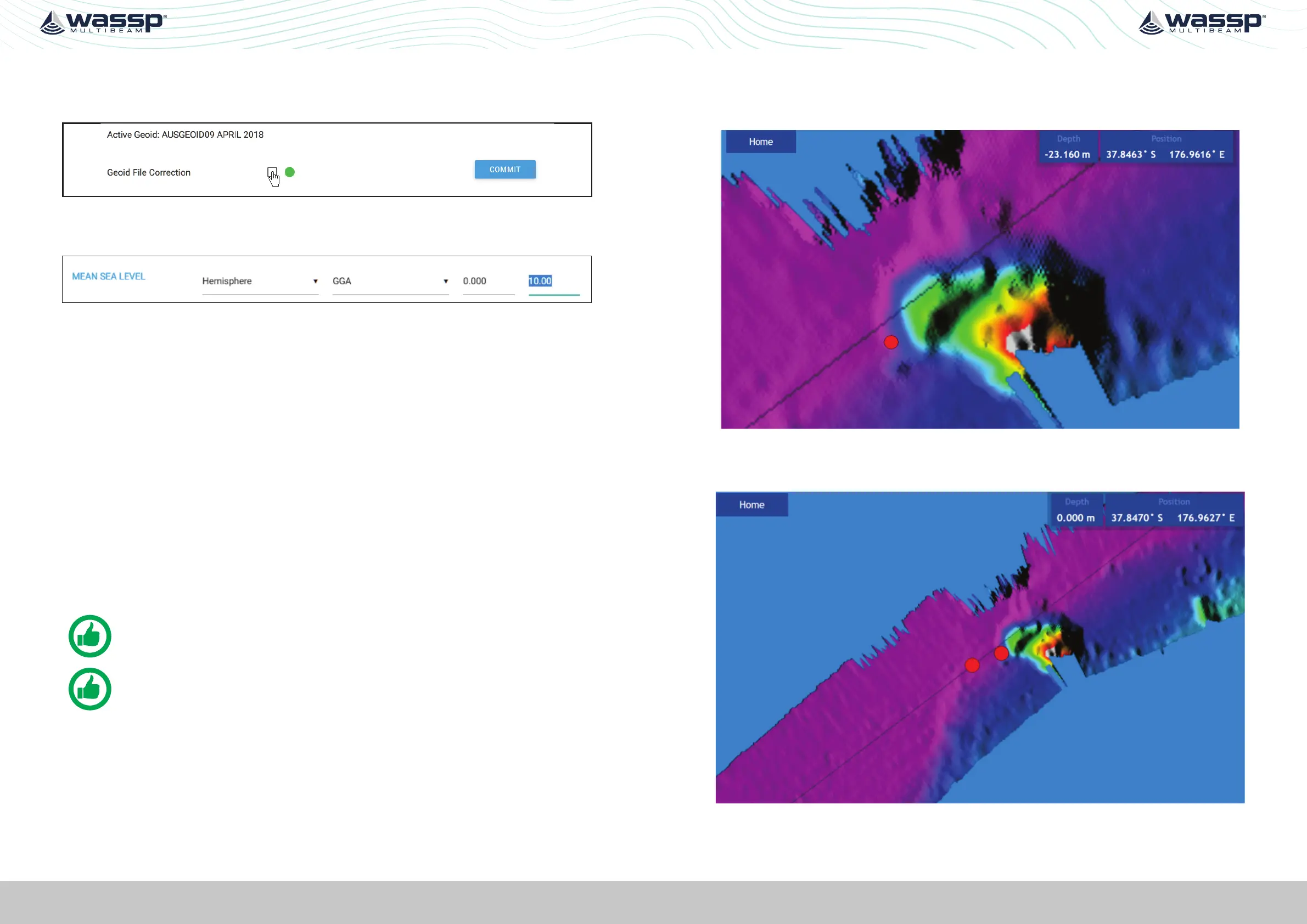
Test 1: For use with standard GPS
To perform this test, find a distinct feature such as a big rock, sharp slope or cable.
1. Run over the distinct object at SOG (e.g. 5kts).
Figure 26. GPS Time Delay Stage 1
2. Run back over object in the opposite direction, same SOG (e.g. 5kts) and drop a mark
on the same spot.
Figure 27. GPS Time Delay Stage 2
 Loading...