Page 52 of 102 Page 53 of 102Doc: DRX Installation
Version: 7.1 January 2021
Doc: DRX Installation
Version: 7.1 January 2021
wassp.com wassp.com
DRX INSTALLATION MANUAL DRX INSTALLATION MANUAL
3. Use the measure tool to measure the dierence between the object’s position in the
direction the vessel traveled. If the object appears earlier than the previous pass, the
time delay is positive.
Figure 28. GPS Time Delay Stage 3
The formula below outlines this process.
adjustment =
( - late / + early ) change in position in metres
speed in knots used in both directions
4. The delay adjustment is added to the current Time Lag (Sec) value in the DATA SETUP
section of the DRX SETUP WEBPAGES. See “5.2.4. Data Setup Tab” on page 39.
Test 2: For use with DGPS
The advantage of this approach over the previous test is that it will eliminate pitch errors.
However, the displacement of the object will be smaller and this will be dicult to
measure accurately as GPS errors can make this impossible.
Approach the distinct feature from the same direction at two vastly dierent known
speeds, as close to zero and at the fastest mapping speed. If the object moves by delta
metres further along the vessel track (+ve) at a faster speed the adjustment to the time
delay will be:
adjustment =
( - late / + early ) 2 x delta
(fast speed in knots) - (slow speed in knots)
5.3.2. Roll Oset
Before attempting a roll patch test it is suggested that the GPS Time lag and any latencies
are accounted for. Also, it is recommended that you conduct a preliminary adjustment
of the Sound Speed settings to get things in the correct ballpark. Configure the mapping
width to be at the maximum 120° for best results.
The WASSP Patch Test Utility, shipped with CDX, can be used to automatically calculate
and apply Roll Oset. Alternatively, Roll Oset can be manually calculated.
Manual Roll Patch Test
1. Use the local chart and local knowledge to identify a spot for the roll patch test –
ideally a flat area between 20-40m (shallower than 10m will make it hard to get an
accurate reading).
2. Run the ship along a line in direction A (it may help to run with the tide and wind
behind the vessel as the return journey is the important one).
3. Turn the ship and make a return journey B so that the same area is mapped but where
the exact opposite heading is used. It may help to use the Heading Up and COG
functions.
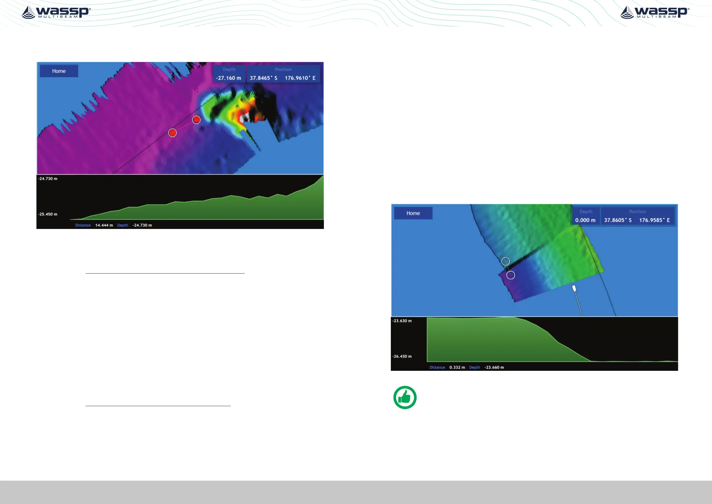
Figure 29. Manual Roll Patch Test
NOTE: Showing path A and path B overlapping. Measurement D is the
change in the depths (2.8m in this case) between the edges of swaths.
4. Use the WASSP CDX Profile tool to measure the depth displacement between the
edges of the swath on one side. This value is D. It will help to stop pinging while
making the measurement so that the swath does not get overwritten.
 Loading...