Page 54 of 102 Page 55 of 102Doc: DRX Installation
Version: 7.1 January 2021
Doc: DRX Installation
Version: 7.1 January 2021
wassp.com wassp.com
DRX INSTALLATION MANUAL DRX INSTALLATION MANUAL
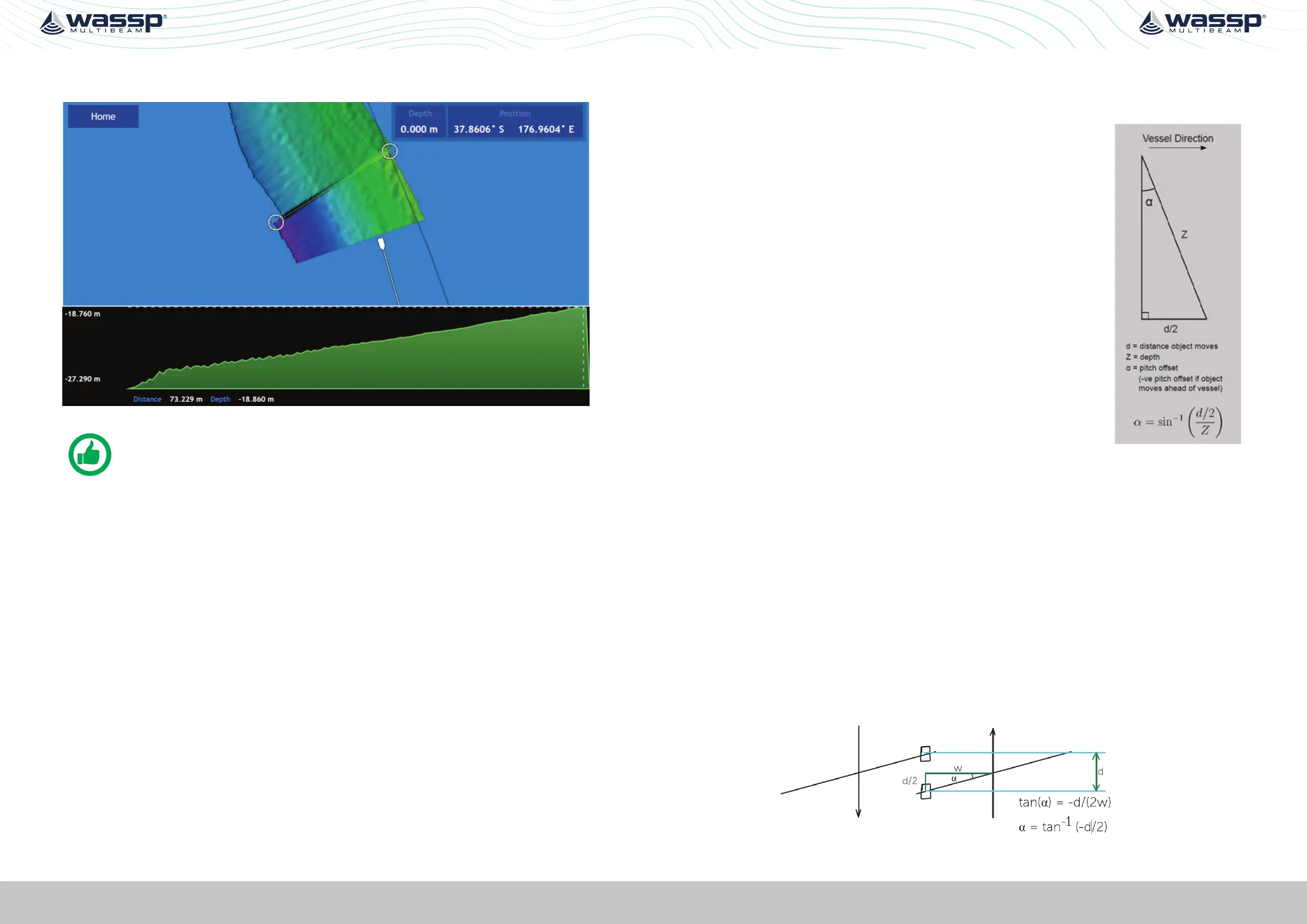
5. Measure the entire width of the swath at the point you have measured the
displacement. This value is H (73.229m in this case).
Figure 30. Measurement of Swath Width H
NOTE: the measurement is the distance of the line in this case rather than
the depth change – this depth change across the swath is not used.
6. Use a calculator (one is present in Windows) to compute tan(a) (D/H) e.g.
a. Run window Calculator, Select ‘View: Scientific Mode’
b. Enter D (e.g. 2.8)
c. Press ‘/’
d. Enter H (e.g. 73.23m)
e. Press ‘=’
f. Select ‘Inv’
g. Press ‘tan
-1
‘
h. Record this number as the Patch Roll Quantity
7. To compute the sign (positive roll or negative roll) of the Roll patch look at the
Starboard side-track as journey B is made.
If this is shallower than track A then the sign for the roll oset is positive. If this is
deeper then the depths from track A the sign for the roll oset is negative.
8. Enter the Roll oset value computed into the Roll Oset setting in the DATA SETUP
section of the DRX SETUP WEBPAGES. See “5.2.4. Data Setup Tab” on page 39.
9. Repeat these steps in a dierent area, or on a dierent Mapping database. If there is
still a significant dierence > 50cm add any dierence generated to the Roll oset
already computed and then test again. It should be possible to generate a roll oset
within 0.1 degrees.
5.3.3. Pitch Oset
If GPS time delay can be completed using variable speed, See ‘Test 2 For use with DGPS’
“5.3.1. GPS Time Delay” on page 50 then attempt to compute pitch oset as follows:
Pitch Correction
Requires: >10m depth, Distinct Object, DGPS or better,
Accurate Time Lag.
1. Once the Time Lag is accurately ascertained using
the variable speed method described in the previous
commissioning step, a Pitch Correction value can be
ascertained by having the Ship travel over a distinct object
in opposite directions.
2. The object will move if the Pitch oset is incorrect and
the use of trigonometry will determine the Pitch oset
between the Motion Sensor and the Transducer.
3. Enter this number into the Pitch Oset in the DATA SETUP
section of the DRX SETUP WEBPAGES. See “5.2.4. Data
Setup Tab” on page 39.
Figure 31. Pitch Corrections
5.3.4. Heading Oset
Requires: DGPS or better, Distinct Object and >10m depth.
To determine an accurate heading correction between the heading sensor and the
transducer orientation we need high accuracy position sensors and corrected seafloor
data.
1. Approach a small, distinct seafloor feature so that the port side of the swath covers
the object.
2. Pass over the object so that the starboard side of the swath crosses the same
object in the opposite direction. It is important that these two tracks are on exactly
parallel heading lines.
3. Use basic trigonometry to calculate the required heading oset that will allow the
object to remain stationary. Redo the heading test to check that the heading oset
was entered correctly.
tan(α) = -d/(2w), α = tan-1 (-d/2)
If object moves as above the sign is negated otherwise remove the -ve sign from this
 Loading...