Page 76 of 102 Page 77 of 102Doc: DRX Installation
Version: 7.1 January 2021
Doc: DRX Installation
Version: 7.1 January 2021
wassp.com wassp.com
DRX INSTALLATION MANUAL DRX INSTALLATION MANUAL
11 APPENDIX
APPENDIX A - CABLE DRAWINGS
APPENDIX A.1 TRANSDUCER RX
Screen / drain wire
Blue and Blue White
Brown and Brown / White
Green and Green / White
Orange and Orange / White
The CAT5E cables used in the
transducer cable follow standard
CAT5 colour codes but the RJ-45
plug wiring is specific to the DRX
and does NOT conform to T568A
or B.
RJ-45 Plug
Pin Number
CAT 5 conductor colour
1 Orange
2 Orange / White
3 Green
4 Green / White
5 Blue
6 Blue / White
7 Brown
8 Brown / White
Case Screen / drain wire (solder)
Pin #1
Pin #8
The screen / drain wire should be soldered on to the side of
the RJ-45 connector. Scratch the side of the connector with
something sharp before soldering to assist with the join.
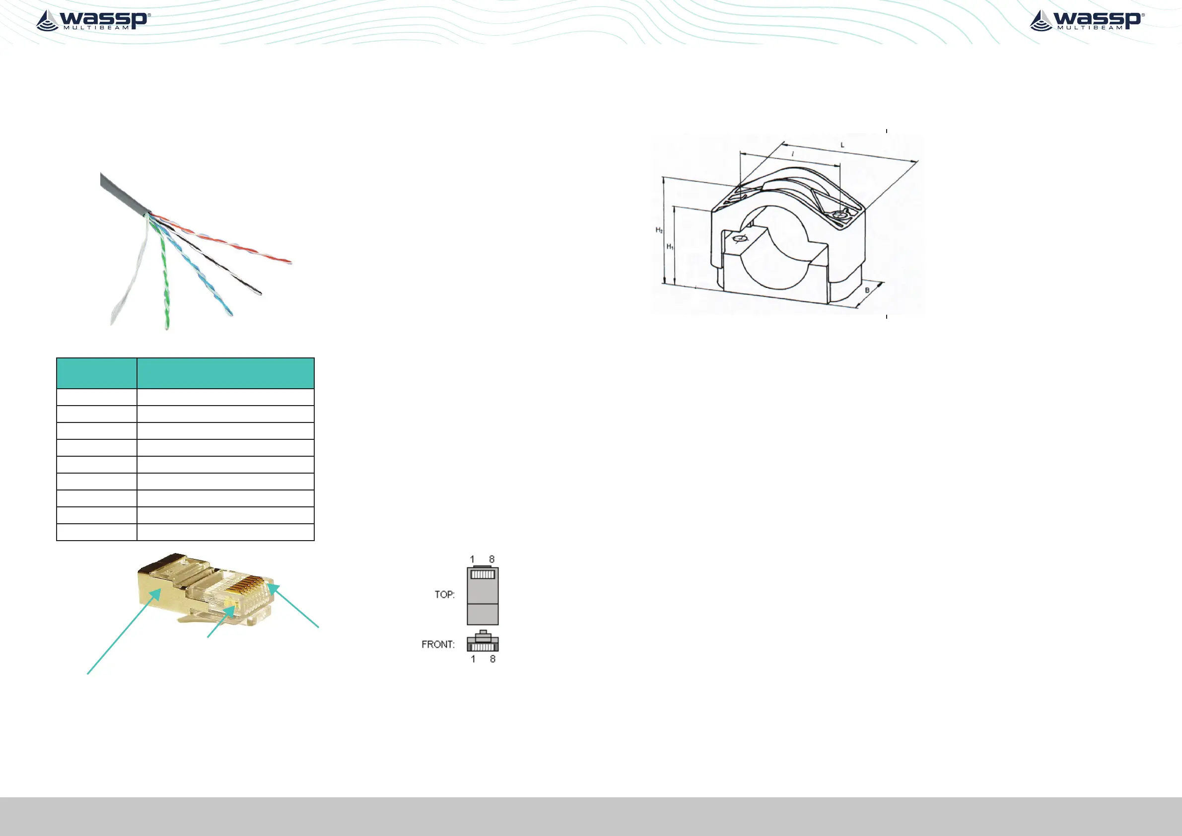
APPENDIX A.2 TRANSDUCER CABLE RESTRAINER
The supplied cable restrainer must be fitted to ensure that transducer connections are
not damaged due to strain from the transducer cable. Ensure that when mounted there
is still room to remove the cables from the DRX for servicing.
 Loading...